Reference
Modification-No.
- 0 -
Page
64
Date
1996 05 10
Install
914 F
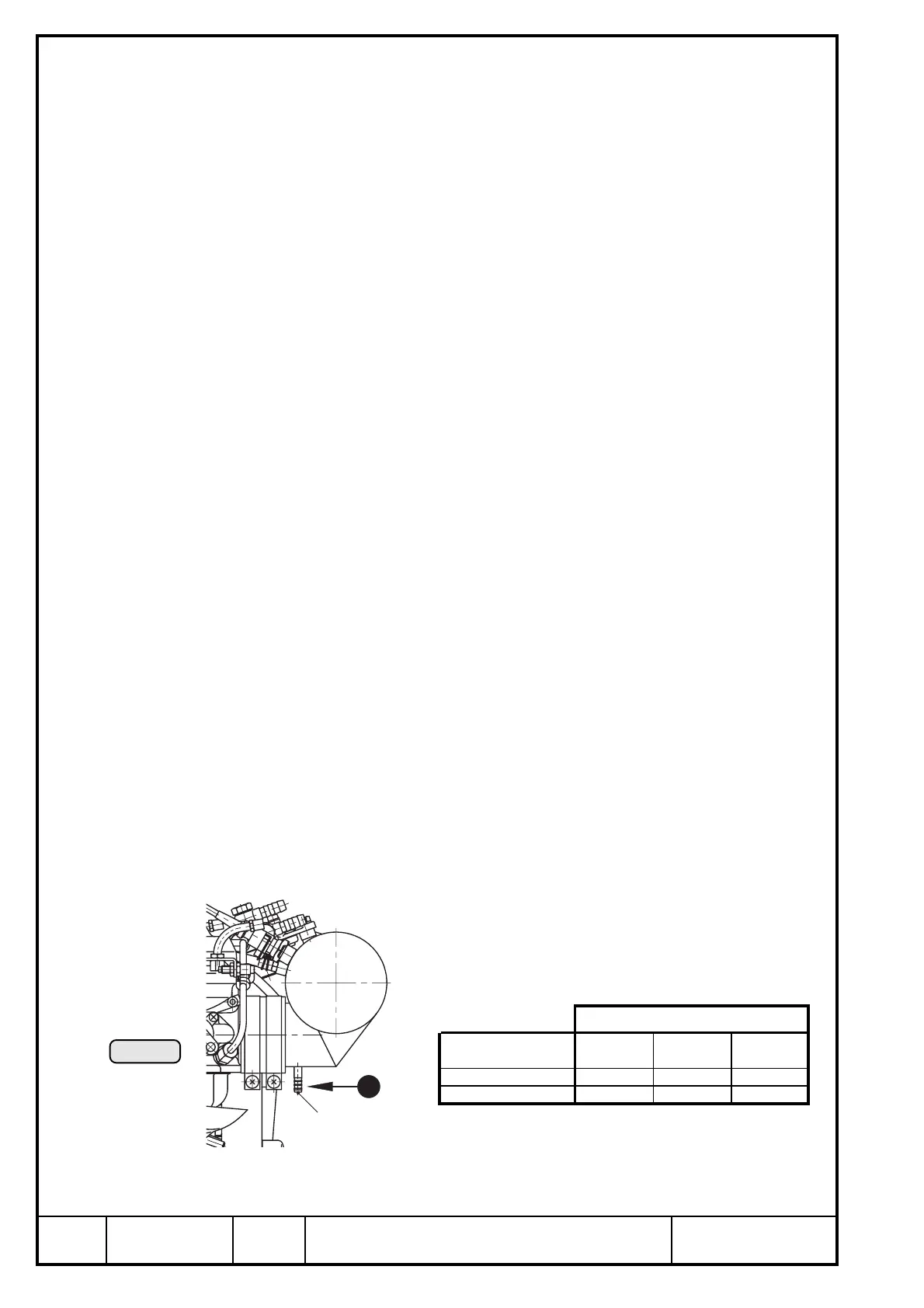
16.2.1) Airbox
See Ill. 44.
The airbox is furnished with 2 drain holes at the lowest position possible.
The holes are necessary to drain fuel from flooding float chambers caused
by badly closing float valve.
◆ NOTE: This drain bores are very small (1,5 mm (1/16") dia.).
Compensation of process conditions is taken care of by the
TCU.
Drainage lines:
▲ WARNING: Connect draining lines without fail, otherwise emerging
fuel could drip onto the exhaust system.
RISK OF FIRE!
➪ The lines have to be routed such that in case of damage the surplus fuel
is drained away suitably.
➪ Route the lines without kinks and avoid narrow bends.
➪ Route the lines with a continuous decline.
➪ The lines have to be protected against any kind of blockage e.g. by
formation of ice.
■ ATTENTION: With closed or blocked drainage bores fuel could flow into
combustion chamber, possibly ruining the engine by hydrau-
lic lock.
Connecting nipple Q of drainage line
outside dia. ø............................ 6 mm (1/4")
slip-on length............................ max. 17 mm (11/16")
■ ATTENTION: Utilize the complete slip-on length. Secure hoses by suitable
screw clamps or by crimp connection.
Location of connecting nipple P2:
P2
1
Ill. 44
axis
connecting nipple x-axis y-axis z-axis
cylinder side 1/3 -568 -180 -20
cylinder side 2/4 -590 180 -20

 Loading...


