Reference
Modification-No.
- 0 -
Page
93
Date
1996 05 10
Install
914 F
23) Connections for instrumentation
These connections to be established in accordance to certification and/or national specifica-
tions.
The certification for connections and connection lines have to be conducted by the aircraft
builder to the latest requirements like FAR and JAR.
For notes regarding the electric rev-counter consult the chapter 19.4.13.
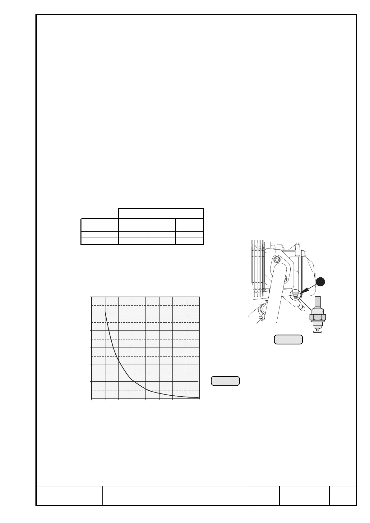
23.1) Sensor for cylinder head temperature:
See Ill. 71/72.
◆ NOTE: A direct reading of the coolant temperature is not provided for.
The temperature sensor Q is directly fitted into cylinder head i.e. a direct temperature
reading of the cylinder head material is taken. This allows the exact measuring of the
cylinder head temperature even in the case of coolant loss.
◆ NOTE: Readings are taken on the hottest cylinder, depending on engine
installation.
➪ location: in the cylinder head of the cylinders 2 and 3, see Ill. 4.
➪ connection: plug for socket 6,3x0,8 to DIN 46247
➪ grounding: via engine block
➪ graph of sensor resistance over temperature
■ ATTENTION: The graph resistance over temperature has been determined, and is
effective at the following conditions only.
ambient temperature: 20° C (68° F)
tolerance: ± 10%
◆ NOTE: BOMBARDIER-ROTAX recommends the temperature indication
VDO instrument “VDO 310.274/082/017“ with an indicating range of
50° to 150° C (120° F - 300° F).
Ill. 72
12010080604020 140 160
1200
1000
(Ω) ohm
(°C)
800
600
400
200
0
Axes
cylinder head x axis y axis z axis
2 -200,0 241,0 -157,0
3 -387,0 -241,0 -157,0
Ill. 71
1

 Loading...


