Reference
Modification-No.
- 0 -
Page
84
Date
1996 05 10
Install
914 F
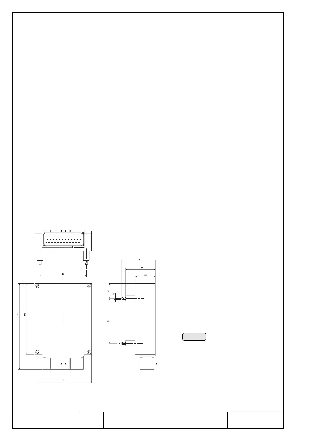
19.4.8) Turbo Control Unit (TCU)
See Ill. 63.
➪ voltage: 12 V/DC min. 6 V
max. 18 V
➪ current input: see chapter 19.5.
◆ NOTE: At wrong polarity of the supply voltage both lamps will light
up.
➪ operating temperature range: min. - 25° C (-13° F)
max. +70° C (+160° F)
➪ storage temperature range: min. - 40° C (-40° F)
max. +70° C (+160° F)
➪ weight: approx. 425 g (1 lb)
➪ dimensions and attachment: see sketch (Ill. 63)
➪ place of installation:
▲ WARNING: Installation in the engine compartment is not permitted
since the TCU is not of a fire resistant construction.
A recommendable location is in the cockpit, below the
instrument panel.
◆ NOTE: Place of installation is limited by the length of the wiring
harness.
Support of the TCU on the 4 silent blocks which ensures an attachment free
of vibrations.
▲ WARNING: If the standard attachment should not be utilized or changed,
certification to the latest requirements such as FAR or JAR has
to be conducted by the aircraft builder.
Ill. 63
▲ WARNING: Choose place of installation such, that operation is within the
specified temperature limits.

 Loading...


