Reference
Modification-No.
- 0 -
Page
76
Date
1996 05 10
Install
914 F
19.3) Description of the Turbo Control Unit (TCU)
See Ill. 53/54.
The ROTAX 914 F engine is equipped with an exhaust gas turbo charger, making use
of the energy in the exhaust gas for precompression of the intake air (boost pressure).
The boost pressure in the airbox is controlled by means of an electronically controlled
flap (waste gate) in the exhaust gas turbine.
◆ NOTE: The waste gate regulates the speed of the turbo charger and
consequently the boost pressure in the airbox.
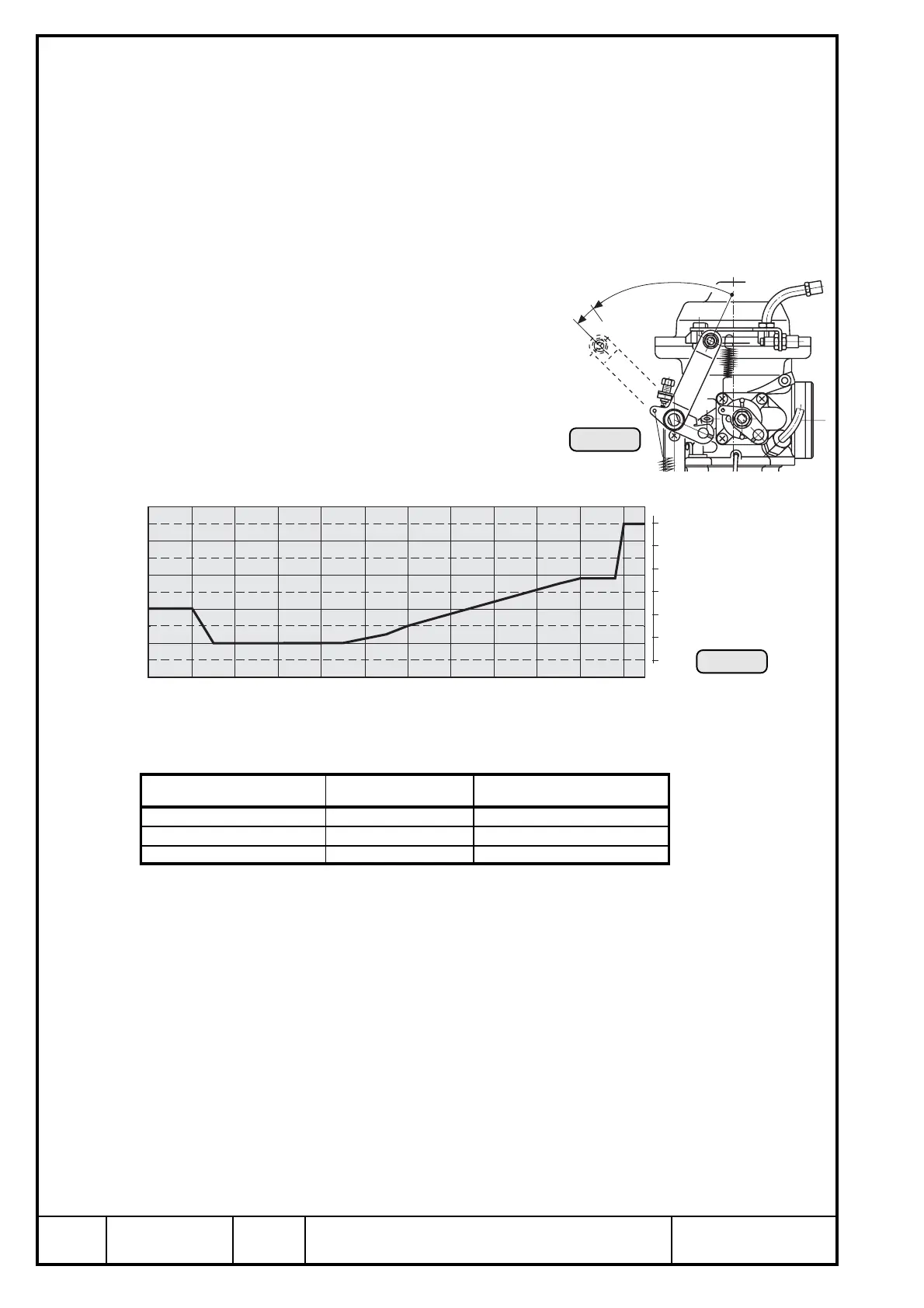
The required nominal boost pressure in the airbox
is determined by the throttle position sensor
mounted on the carburetor 2/4. The sensor's
transmitted position is linear from 0 to 115%
corresponding to a throttle position from idle to full
power. See ill. 53.
For correlation between throttle position and nomi-
nal boost pressure in the airbox, refer to the
diagram (ill. 54).
28
1400
1300
1200
1100
1000
900
hPa
0 10 20 30 40 50 60 7 0 80 90 100 110 115 %
30
32
34
36
38
40 in. HG
100%
115%
0%
Ill. 54
Ill. 53
The most important points for engine operation:
■ ATTENTION: As shown in the diagram, the throttle position at 108 ÷ 110 % results
in a rapid rise of nominal boost pressure. To avoid unstable boost, the
throttle should be moved speedily through this area either to full
power (115 %) or, on a power reduction, to max. continuous power.
In this range (108 - 110 % throttle position) small changes in throttle position have a
big effect on engine performance and speed, but are virtually not apparent for the pilot
from the throttle lever position.
■ ATTENTION: The exact setting for a specific performance is virtually impossible in
this range and has to be prevented, as it might cause control
fluctuations (surging).
engine performance throttle position nominal airbox pressure
idling of engine ~ 0 % 1100 hPa (32,5 in. HG)
max. continuous performance 100 ÷ 108 % 1190 hPa (35,1 in. HG)
take-off performance 110 ÷ 115 % 1350 hPa (39,9 in.HG)

 Loading...


