Reference
Modification-No.
- 0 -
Page
46
Date
1996 05 10
Install
914 F
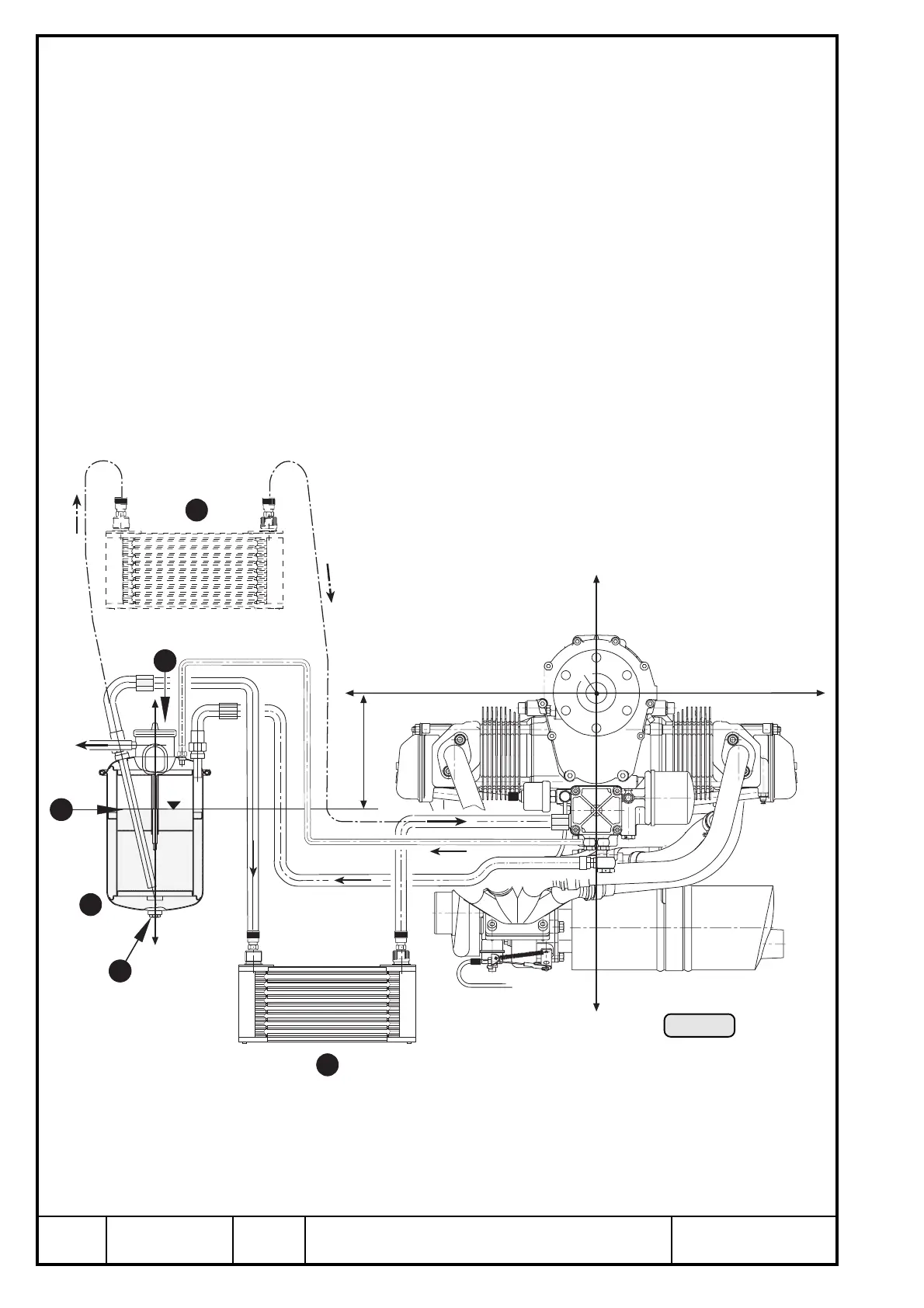
13.5) Feasible position and location of the oil tank
See illustration 29.
➪ The longitudinal axis z3 to be parallel to z-axis of the system of coordinates.
Tolerated deviation of parallelism: ± 10°
◆ NOTE: Above notice is valid for both planes.
➪ The oil tank Q has to be positioned in its z-axis such that the oil level W is always
between 0 and -400 mm on the z-axis .
▲ WARNING: At higher location of the oil tank oil might trickle through clearances
at bearings into crankcase during longer periods of engine stop. If
fitted too low it might badly effect the oil circuit.
➪ Install the oil tank free of vibrations.
➪ Oil tank cover E and oil drain plug to be easily accessible.
Ill. 29
+z
-z
-y
+y
P
+z3
-z3
max. 400 mm
4
2
1
3
5
5

 Loading...


