Reference
Modification-No.
- 0 -
Page
26
Date
1996 05 10
Install
914 F
10.2) Permissible fitting positions
See Ill. 11/12/13.
To simplify the matter, reference is made only to the 2 engine attachment points R1,
L1 and the 2 turbo charger attachment points R(T)2 and L(T)2.
Location of the 2 turbo charger attachment points R(T)2 und L(T)2.
◆ NOTE: All dimensions to point of reference (P) and the system of coordi-
nates remain unchanged.
The following details of engine position are with reference to aircraft on ground,
ready for take off.
➪ engine suitable for propeller in tractor or pusher arrangement,
➪ propeller shaft above cylinders. See ill. 2.
▲ WARNING: For upside down installation of the engine, the lubrication system,
fuel system and the cooling system are unsuitable!
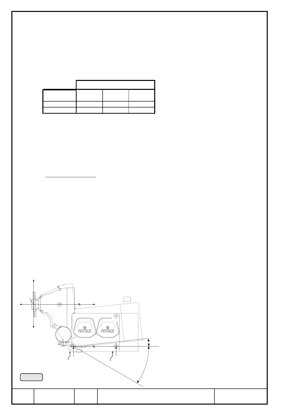
Longitudinal axis:
➪ The centre of the attachment points L1 and L(T)2 must be on axis x2 parallel to
the x axis.
Allowable pitch deviation of parallelism of axes:
max. 6° counter-clockwise, on ground
max. 10° counter-clockwise, in operation
max. 30° clockwise (see ill. 11)
▲ WARNING: On installations with fuel tank located above carburetor level com-
bined with badly closing carb float valve, fuel could pass into
cylinders at more than 6° decline of propeller shaft axis after longer
periods of downtime. See FAR, § 33.17.
To prevent a possible hydraulic shock at engine start, ensure proper
closing of float valves. If in doubt, park the aircraft with rising propeller
shaft axis.
Axes
attachment
point
x axis y axis z axis
L(T)2 -414,3 71,0 -211,0
R(T)2 -414,3 -71,0 -211,0
Ill. 11
+z
-z
+x
-x
P
L1
R1
L(T)2
R(T)2
x2
6°
30°
6°

 Loading...


