Reference
Modification-No.
- 0 -
Page
50
Date
1996 05 10
Install
914 F
14.4) Connecting dimensions, location of joints and directives for installation
14.4.1) Electric fuel pump
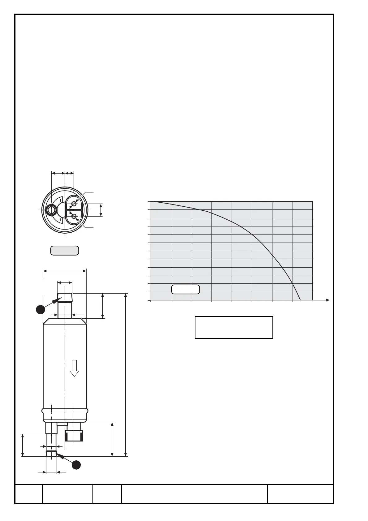
See outline of fuel pump, Ill. 30, Ill. 31 and 32.
Design: self priming vane pump
Volume of supply: electric fuel pump with attachment kit, 2 hose clamps and
various attachment elements
Weight: 0,35 kg (.8 lb) inclusive attachment items
Fitting position: horizontal or vertical
Connections: See Ill. 31.
Inlet Q (suction side)
Outlet W (pressure side)
■ ATTENTION: Utilize the complete slip-on length on all hose connections.
Secure fuel hoses with suitable screw clamps or by crimp
connection.
Delivery rate/pressure : See diagram Ill. 32.
The diagram shows the delivery rate of the electric fuel
pump over pressure.
Take note of the following:
➪ diagram outlines min. capacity at nominal voltage on
pump
➪ pressure and suction head are "ZERO"
➪ graph is effective on the seasoned pump only, running-
in period approx. 30 min.
◆ NOTE: A capacity increase of approx. 20% is
feasible by running-in process.
ø38
ø13,3
ø12
ø9
20 (±0,5)
30
141,5 (±3)
22
ø8
11,75
8
11
M5
M4
P1
P2
∆
P
0
10
20
30
40
50
60
70
80
90
100
110
120
0 250 500 750 1000 1250 1500
1750 2000 hPa
l/h
Ill. 31
Ill. 32
1
2
∆P= P2 – P1

 Loading...


