Reference
Modification-No.
- 0 -
Page
97
Date
1996 05 10
Install
914 F
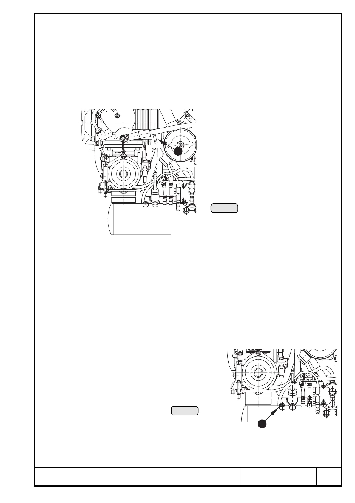
23.5) Monitoring of the intake manifold pressure
See Ill. 79.
Connection nipple Q to measure manifold pressure:
outside dia. ø ................ 6 mm (1/4")
slip-on length . max. 17 mm (11/16")
■ ATTENTION: Utilize the total slip-on length on all joints. Secure hose by suitable
screw clamps or crimp connection.
▲ WARNING:
Protective covering to be utilized for trans-
port and at engine installation only. If
connection for pressure reading is not
employed it has to plugged suitably.
■ ATTENTION: Flawless operation of the indicating instrument needs the installa-
tions of a water trap between engine and instrument for the fuel
condensate.
23.6) Air temperature in the airbox
See Ill. 80.
To take air temperature readings in the airbox a connection is provided. This
connection is closed on the standard engine by a plug screw.
➪ connection: tapping 1/8-27 NPT
thread length approx. 9 mm (3/8")
1
Ill. 79
Ill. 80
1

 Loading...


