Reference
Modification-No.
- 0 -
Page
78
Date
1996 05 10
Install
914 F
Requirements for flawless operation of the rectifier-regulator
➪ the rectifier-regulator has to be protected by a slow blowing 30A fuse.
➪ cross section of the main circuit of at least 2,5 mm
2
➪ a capacitor (Ill. 52 Pos.A) of at least 22 000 µF / 25 V is necessary.
➪ the voltage difference between battery and terminal C of regulator should be
less than 0,2 V.
Use cables in this area as short as possible and with adequate cross
section.
➪ never sever connection between terminal C and +B of regulator e.g. by
removal of a fuse
➪ type: electronic full-wave rectifier regulator
➪ effective voltage: 14 ± 0,3 V (from 1000 ± 250 r.p.m.)
➪ current limit: max. 28 A
➪ ambient
temperature range: min. -25° C (- 13° F)
max. +90° C (194° F)
➪ weight: 0,3 kg (.66 lb)
➪ 2 flexible cables, 1,5 mm
2
yellow (in shielding metal braid)
➪ length approx. 660 mm (26 in) starting from ignition housing
➪ with on each plug socket 6,3 x 0,8 to DIN 46247
◆ NOTE: approx. 250W AC output at 5800 r.p.m.
For DC output in connection with rectifier-regulator see chapter
19.4.2.
ge
ge
Cyl. 1
Cyl. 3
Cyl. 2
Cyl. 4
19.4) Technical data and connection of the electric components
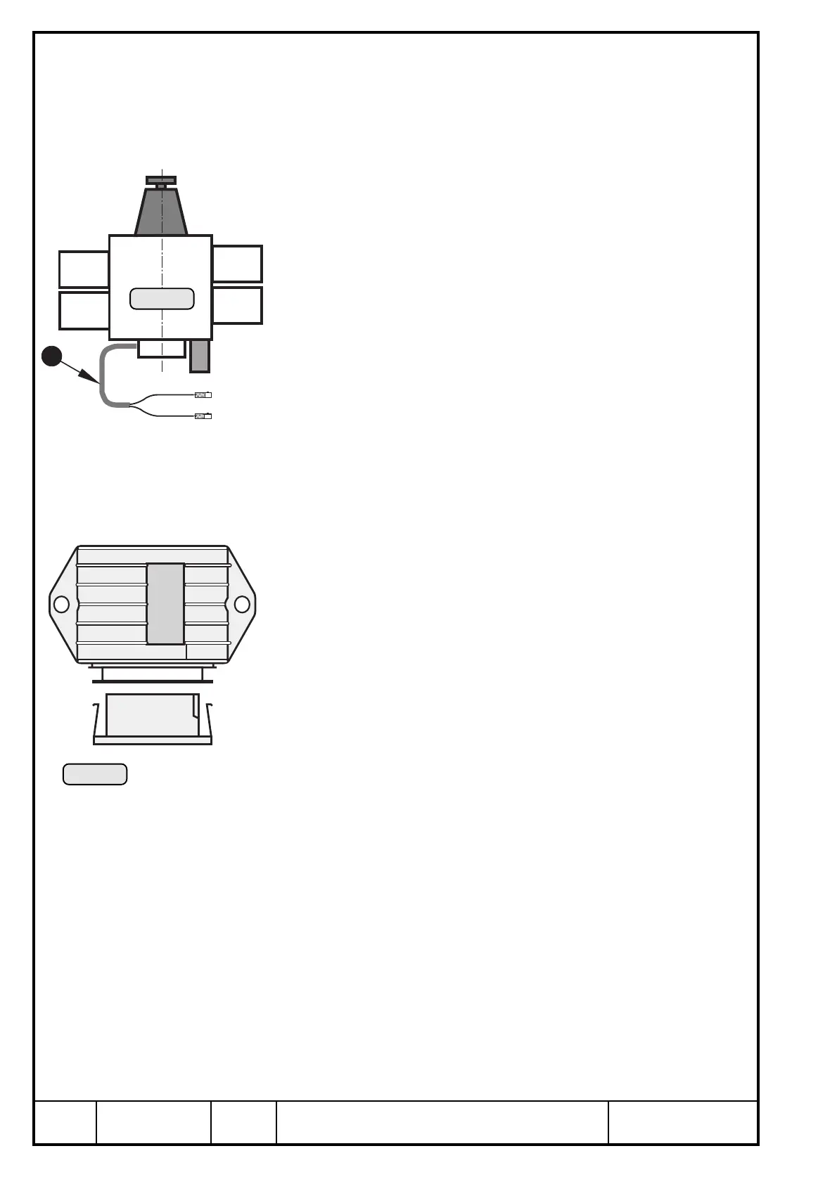
19.4.1) Integrated generator
See Ill. 55
Feeding wires Q from the generator to rectifier-regulator on left side of
ignition housing (see ill. 55).
Ill. 55
GGR+BLC
GIALLO
GIALLO
ROSSO
BATT
LAMP
CHIAVE
GGR+BLC
DUCATI
12VDC
Ill. 56
19.4.2) Rectifier-regulator
See Ill. 56/57.
1

 Loading...


