Reference
Modification-No.
- 0 -
Page
82
Date
1996 05 10
Install
914 F
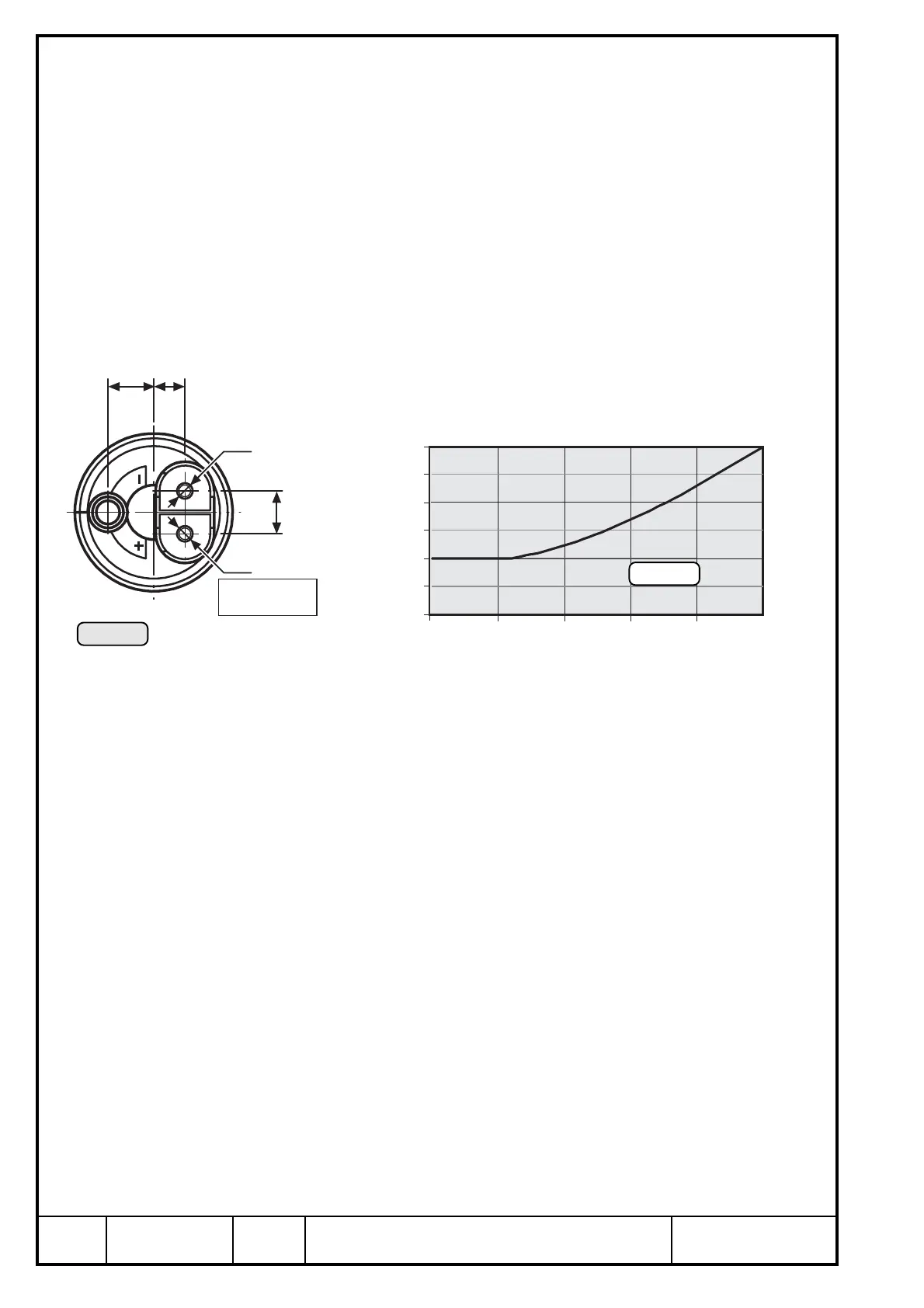
19.4.7) Electric fuel pumps
See Ill. 61/62.
➪ installation: see fuel system, chapter 14
➪ voltage: 12 V/DC
➪ connections: + terminal: M 4 screw connection
-
terminal: M 5 screw connection
suitable for cable eyes to DIN 46225
For radio interference suppression a capacitor (Ill. 52 Pos.) of 1µF / 100 V has
to fitted as near as possible to the terminals.
▲ WARNING: The certification to the latest requirements such as FAR or
JAR has to be conducted by the aircraft builder.
➪ current input:
The diagram shows the current input over pressure.
11,75
8
11
M5
M4
+
Anschluß
connector
Ill. 61
1,5
2,0
2,5
3,0 A
250
500
750
1250 hPa
0
1000
Ill. 62
Take note of the following:
➪ The diagram outlines minimum capacity at nominal voltage on pump.
➪ Pressure- and suction head are "ZERO".
➪ Graph is effective on a seasoned pump only, running-in period approx. 30
min.
➪ Fuse:
Each of the two fuel pumps has to be protected by y slow blowing 5A fuse
in accordance with wiring diagram (Ill. 52).
▲ WARNING: All connections have to be established by the aircraft builder
in compliance with regulations such as FAR or JAR and the
effective wiring diagram (Ill. 52).
▲ WARNING: An essential point is according to regulations, that the fuel
pumps are connected on two completely independent power
supplies.

 Loading...


