Reference
Modification-No.
- 0 -
Page
94
Date
1996 05 10
Install
914 F
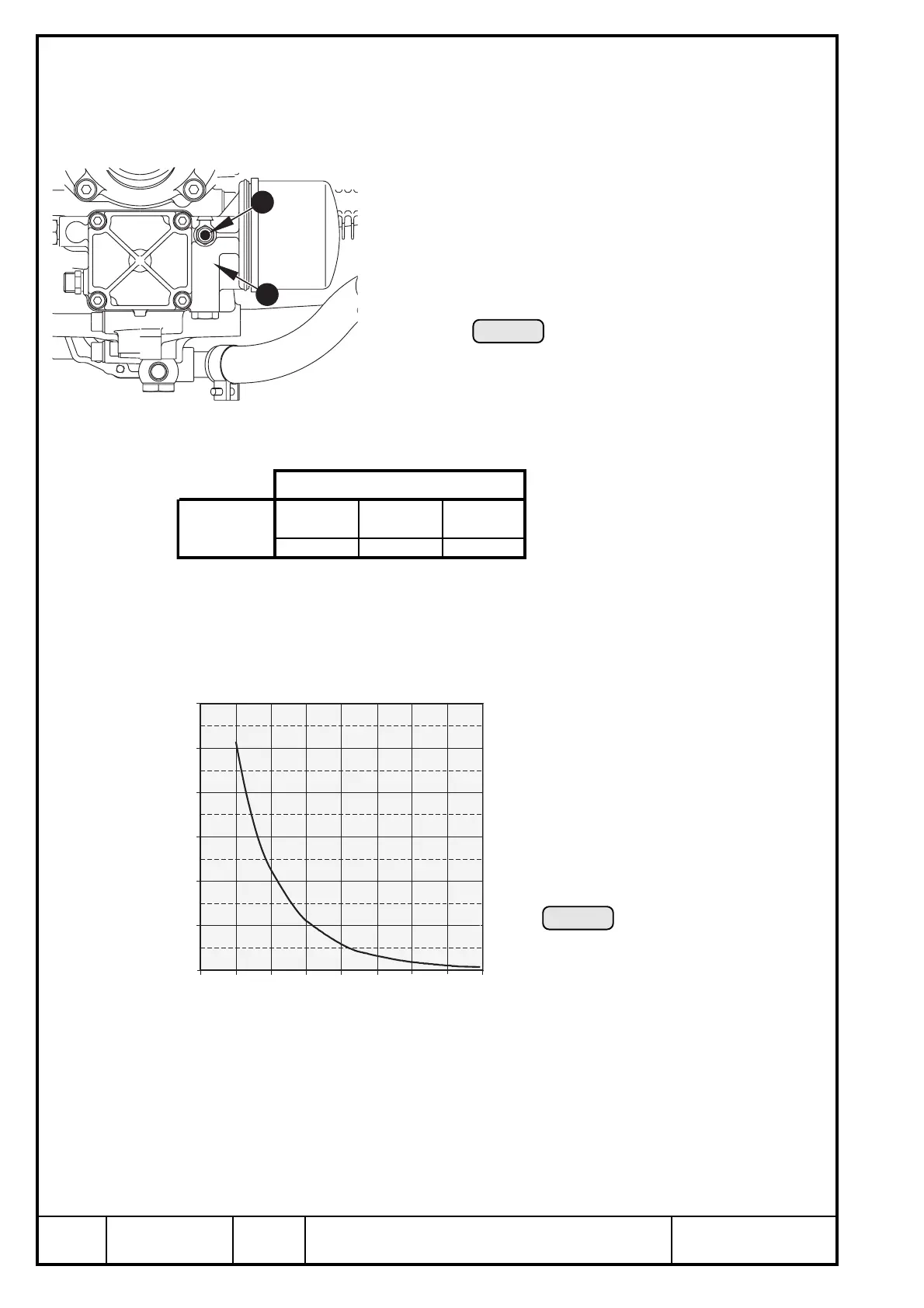
23.2) Sensor for oil temperature:
See Ill. 73/74
➪ location: oil pump housing
➪ marking W: marked with "TO" on oil pump flange
■ ATTENTION:
To avoid any mix-up with indication wiring, mark this
particular cable also with "TO".
➪ position of the temperature sensor Q on the oil pump flange:
➪ connection of
sensor wiring: plug for socket 6,3 x 0,8 to DIN 46247
➪ grounding: via engine block
➪ graph of sensor resistance over temperature
Ill. 73
TO
Axes
x axis y axis z axis
-115 46 -150
point of
support
Ill. 74
12010080604020 140 160
1200
1000
(Ω) ohm
(°C)
800
600
400
200
0
2
1
■ ATTENTION: The graph resistance over temperature has been determined, and
is effective at the following conditions only.
ambient temperature: 20° C (68° F)
tolerance: ± 10%
BOMBARDIER-ROTAX offers a non-certified temperature indicating instrument.
Refer to current spare parts list.
▲ WARNING: Certification to the latest requirements such as FAR of JAR has to be
conducted by the aircraft builder.

 Loading...


