Reference
Modification-No.
- 0 -
Page
38
Date
1996 05 10
Install
914 F
12.8) Cooling air ducting
Contrary to the cylinder heads, the cylinders are ram air cooled. Plan cooling air ducting
according to installation requirement.
▲ WARNING: The cooling air ducting has to be designed and built such, that the operating
temperatures are kept within the specified limits, warranted even at hot day
conditions.
12.8.1) General directives for ducting of the cooling air
See illustration 2/3/4.
For front installation in a closed fuselage, ducting of cooling air to the cylinders is
recommended. In this case a costly horizontal partitioning can be avoided.
BOMBARDIER-ROTAX developed especially for this application a non-certified
cooling air ducting.
▲ WARNING: Certification to the latest requirement like FAR or JAR has to be
conducted by the aircraft builder.
The following recommendations should assist the aircraft builder at the plan-
ning of a suitable cooling air ducting.
➪ The cooling air ducting to be adequate to transfer thermal energy of c. 6 kW (5,7
BTU/s) at take-off power.
➪ required cross section of air duct: at least 100 cm
2
(16 in
2
)
➪ material:
glass fibre reinforced plastic or heat resistant non-inflammable material.
➪ attachment:
formlocking on engine case and cylinders
◆ NOTE: In case formlocking attachment won`t be adequate, additional at-
tachment is possible on two tapped lugs M8 on top side of engine.
■ ATTENTION: The stated limit loads are valid only at utilization of min specified
thread length, and must never be exceeded.
Depth of thread 18 mm (11/16").
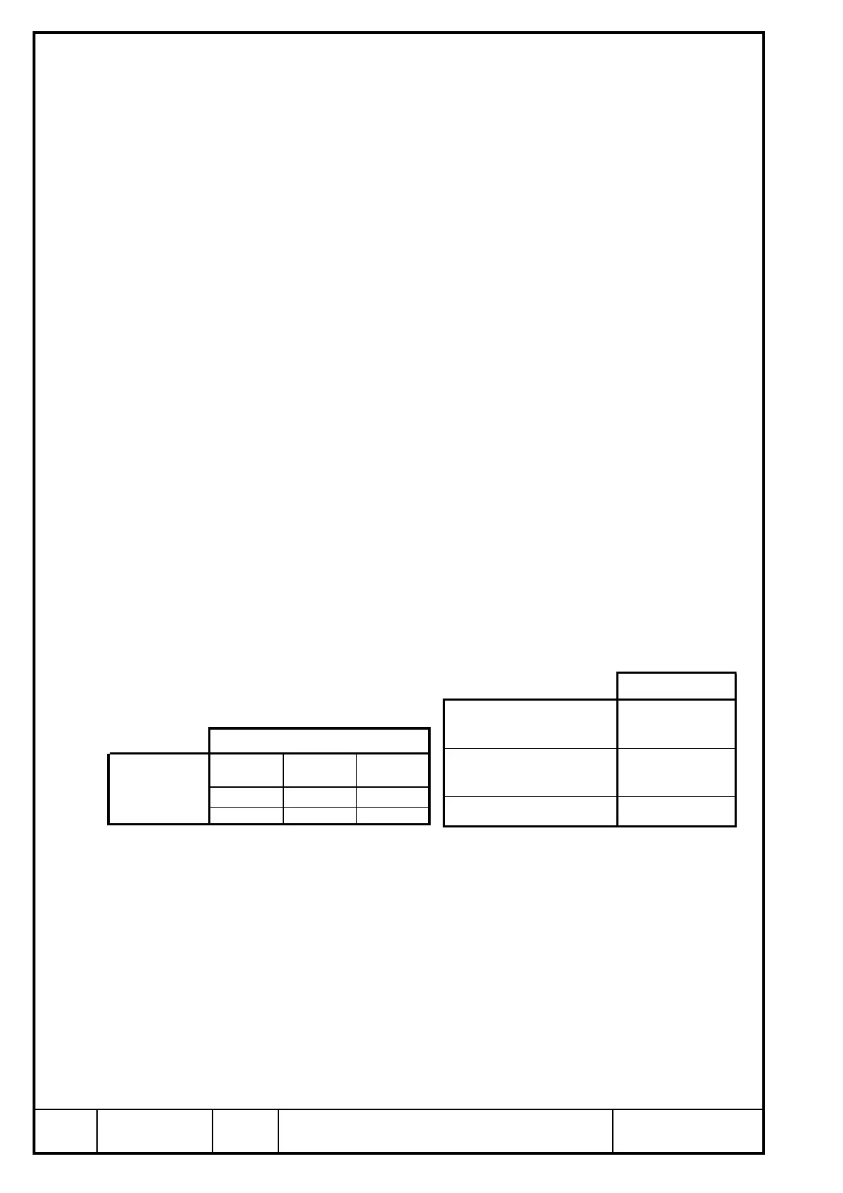
attachment points
max. allowable forces (limit
load) in (N) in x, y and z axis
2 000
max. allowable bending moment
(limit load) in (Nm) in x, y and
z axis
50
min. length of thread engagement
(mm)
15
Axes
x axis y axis z axis
-300,0 -30,0 -14,0
-300,0 30,0 -14,0
attachment
points

 Loading...


