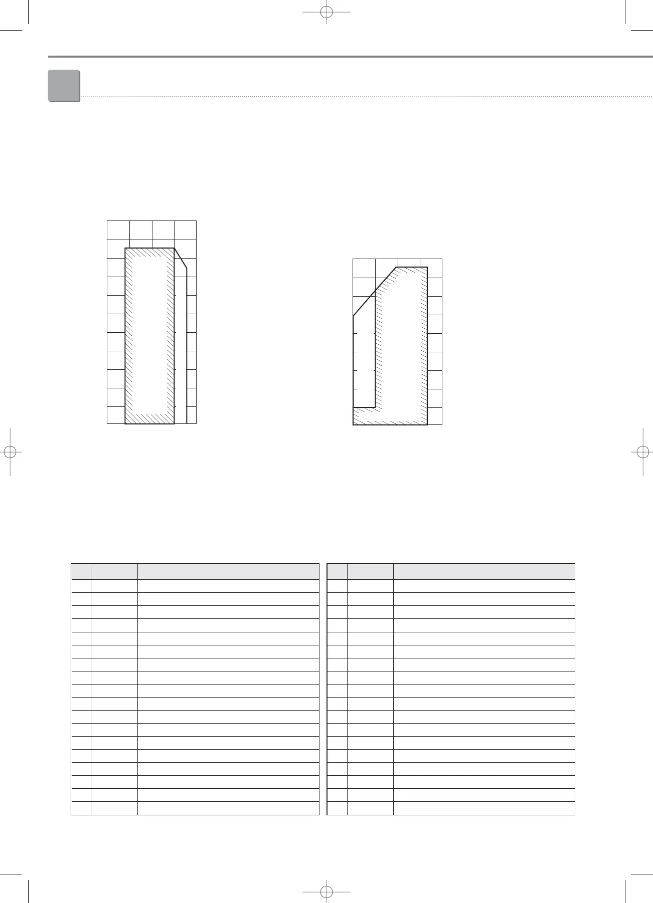
Indoor temperature(ºCDB)
Outdoor temperature (ºCWB)
Range for
continuous
operation
Range for warming up operation
1-9. Cycle operation mode
1) Description of cycle function parts
No Classification Description
1 A DVI (Digital Vapor Injection) compressor
2 B FVI (Fixed Vapor Injection) compressor 1
3 C FVI (Fixed Vapor Injection) compressor 2
4 D PWM solenoid valve
5 E Discharge temperature sensor of DVI compressor
6 F Discharge temperature sensor of FVI compressor 1
7 G Discharge temperature sensor of FVI compressor 2
8 H Oil separator
9 I Capillary tube from oil separator
10 J High pressure switch
11 K Hot gas bypass solenoid valve
12 L Check valve
13 M High pressure sensor
14 N Reversing solenoid valve (4way valve)
15 O Heat exchanger of outdoor unit (Condensing unit)
16 P Ambient air temperature sensor
17 Q Cond_out temperature sensor
18 R Main EEV 1 ( For heating operation)
No Classification Description
19 S Main EEV 2 ( For heating operation)
20 T Check valve
21 U Liquid bypass solenoid valve
22 V EVI EEV
23 W Turbo Intercooler
24 X EVI_in temperature sensor
25 Y EVI_out temperature sensor
26 Z Liquid tube temperature sensor
27 a EVI bypass pilot solenoid valve
28 b Suction temperature sensor
29 c Accumulator
30 d Accumulator CCH (Crank Case Heater)
31 e Oil solenoid valve 1
32 f Oil solenoid valve 2
33 g Oil solenoid valve 3
34 h Oil balancing service valve between units
35 i Low pressure sensor
36 j Check valve
3-1.DVM,HR3_Outdoor(238~293) 3/21/08 11:21 Page 274