A
B
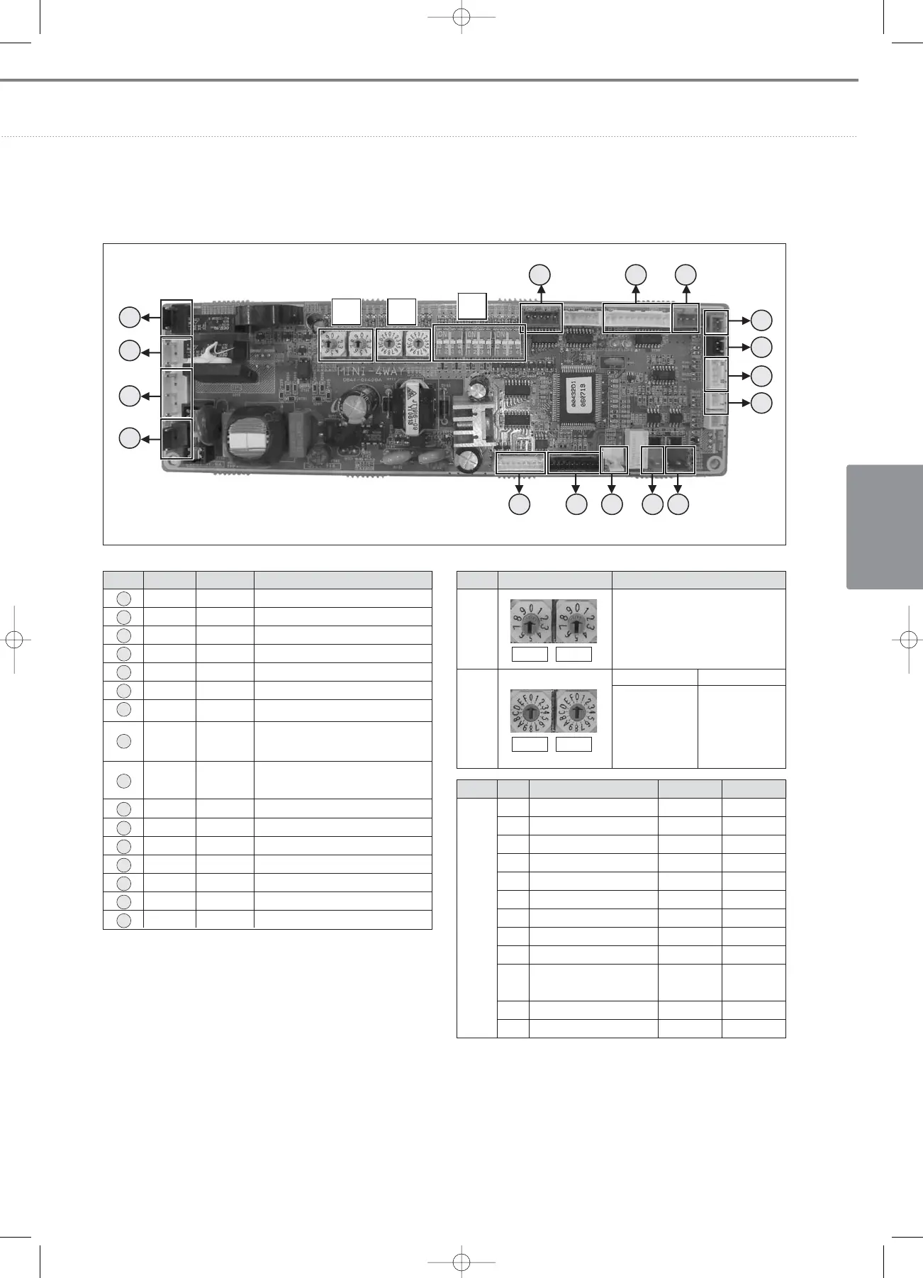
No.
SW01 SW02
S/W
Main Address Setting
(00~63)
FUNCTION
SW03 SW04
SW03
Address of
Interface
Module
Channel 0~2
SW04
Group Address
(RMC) for
Centralized
Control 0~F
No. CN # COLOR FUNCTION
1 CN62 Blue EEV
2 CN60 White Louver
3 CN81 Red
Error Check, Indoor unit Operation
4 CN83 Red External Contact Control
5 CN51 Black Float Switch
6 CN41 White Room Sensor, Eva-In Sensor
7 CN42 White Eva-Out Sensor
9 CN33 Blue
Communication with Wired
Remote Controller (COM2)
8 CN31 Red
Communication with
Outdoor Units (COM1)
10 CN32 White
DC12V for Wired Remote Controller
11 CN10 Black MICOM Download
12 CN91 White Display
13 CN71 Blue AC 230V Input
14 CN78 White Fan Motor
15 CN74 White Drain Pump
16 CN75 Black Ventilator
C
No. S/W FUNCTION ON OFF
K1 - - -
K2 Centralized Controller Not use Use
K3 RPM Up N/A N/A
K4 Optional Drain Pump N/A N/A
K5 Heating Thermo-off +5°C +2°C
K6 Filter Signal Display 1,000hrs 2,000hrs
K7 Hot Water Coil N/A N/A
K8 Electrical Heater N/A N/A
K9 Min. EEV Step at Heating Fixed 80 step 0 or 80 step
K10
Priority of Indoor unit Display
Slave
on Wired Remote Controller
(Default)
Master
K11 External Contact Control Not use Use
K12 - - -
chapter2_Indoor units(002-051) 3/14/08 22:09 Page 31