V-131
C
ONTROL
S
YSTEMS
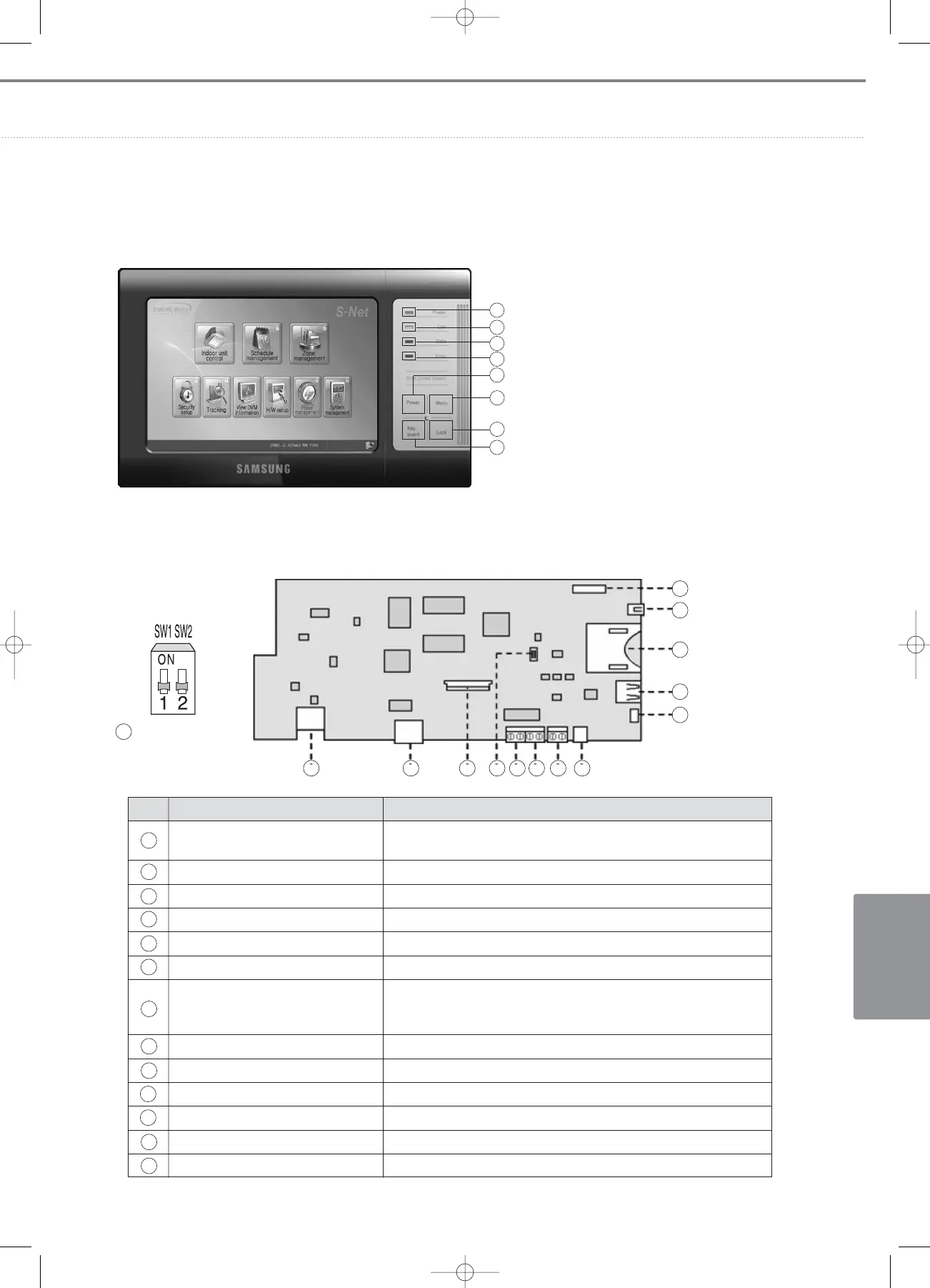
3) Main panel
4) Connectors
1
2
3
4
5
6
7
8
Power LED
LAN LED
Data LED
Error LED
Power switch – Press the S-NET mini to turn ON
Menu switch – It shows the main menu
window to users.
Lock switch – Undesirable key press protection
Keyboard switch – Press the keyboard switch
to show the keyboard
No. Name Description
System debugging connector
RS232 interface for system configuration, data management and
software debugging
LAN connector LAN connection to DMS
Touch screen interface Touch panel signal interface
Option switch Control specification setting for external inputs
External input 1 Mechanical contact input1 (Load : 12VDC/5mA)
External input 2 Mechanical contact input2 (Load : 12VDC/5mA)
RS485 connection to centralized controllers or interface modules.
RS485 connector It has polarity which causes error in communication with lower-layer
devices if reverse-polarized connection is made.
Power supply connector 12VDC, 3A
Software upgrade connector For software upgrade of system debugging engine
USB interface USB interface for a key board or memory stick
Flash memory card SD-type flash memory interface for data back-up
1394 interface IEEE 1394 interface
Bootload connector For OS bootloading
1
2
3
4
5
6
7
8
10
11
12
13
9
Option switch
4
1 2 3 4 5 6 7 8
9
10
11
13
12
05-3_control systems(082~141) 3/6/08 14:04 Page 131