Control Systems
V-34
1
1
Individual control system
1-3. Wired remote controller
4) MWR-VH01
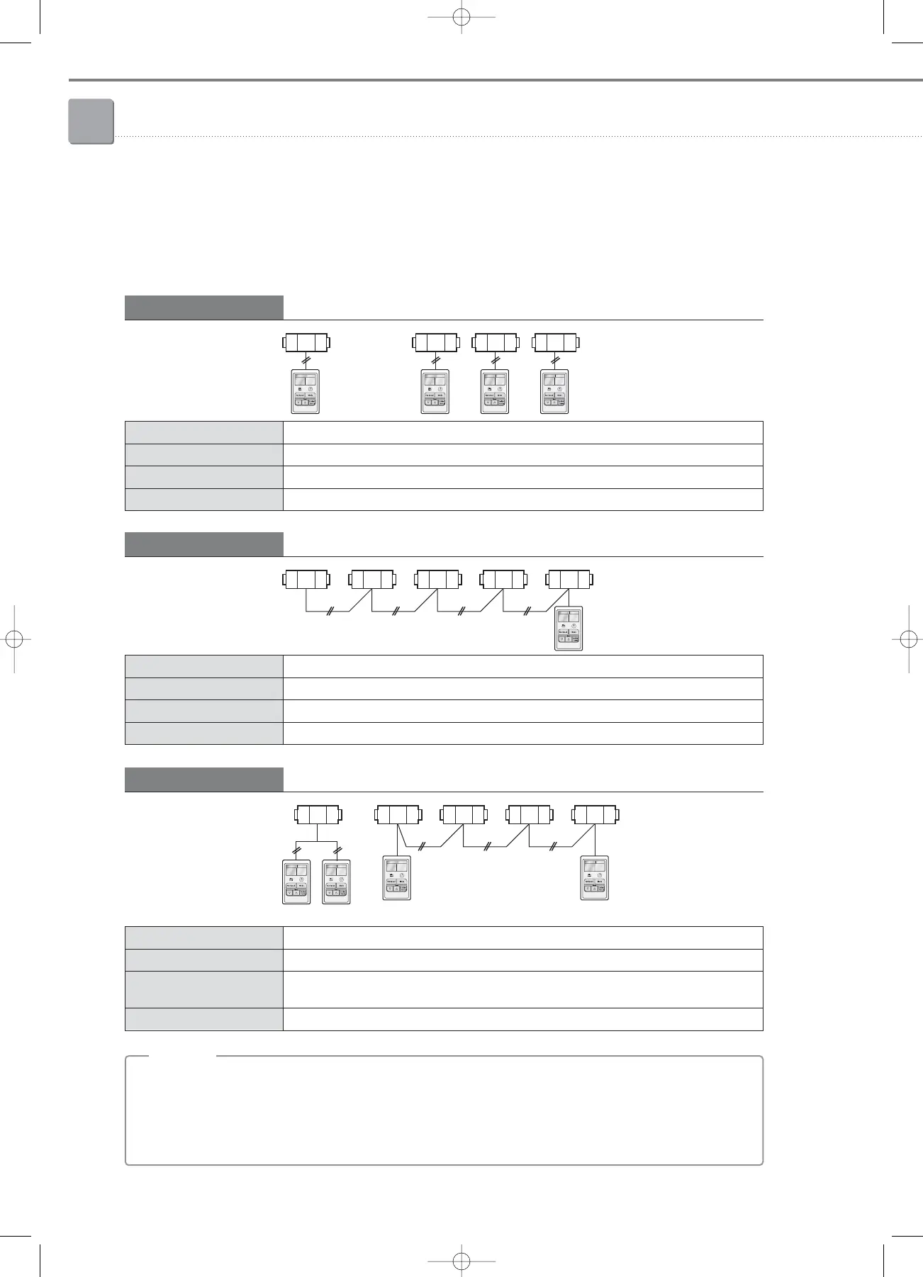
(5) Connection examples
Individual control
Control 1 ERV with 1 wired remote controller
Connection 1 : 1
Control Connected ERV
Display Operation status of the connected ERV
Error occurrence Displays an ERV error.
ERV
Wired R/C
Group control (1)
Control multiple ERVs with 1 wired remote controller
Connection 1 : N (Max. 16 ERV units)
Control All connected ERVs
Display Operation status of one connected ERV on a random basis.
Error occurrence Displays the error if there is an error occurred in one of ERVs.
ERV
Wired R/C
Group control (2)
Control multiple ERVs with 2 wired remote controllers
Connection 2 : N (Max. 16 ERV units)
Control All connected ERVs
Display
Two remote controllers display identical operation status of one connected ERV on a random
basis.
Error occurrence Displays the error if there is an error occurred in one of ERVs.
ERV
Wired R/C
• Applicable model : ERV
• Power (V1/V2) : DC 12V / 50mA
• Communication (F3/F4) : RS485 communication (non-polarity), VCTF (0.75~1.5mm
2
)
• No. of ERVs possible to connect to 1 ERV remote controller : max. 16 units
;
NN
NN
oo
oo
tt
tt
ee
ee
Master Slave
Slave
05-1_control systems(002~045) 3/15/08 4:09 Page 34
 Loading...


