Control Systems
V-38
1
1
Individual control system
1-3. Wired remote controller
4) MWR-VH01
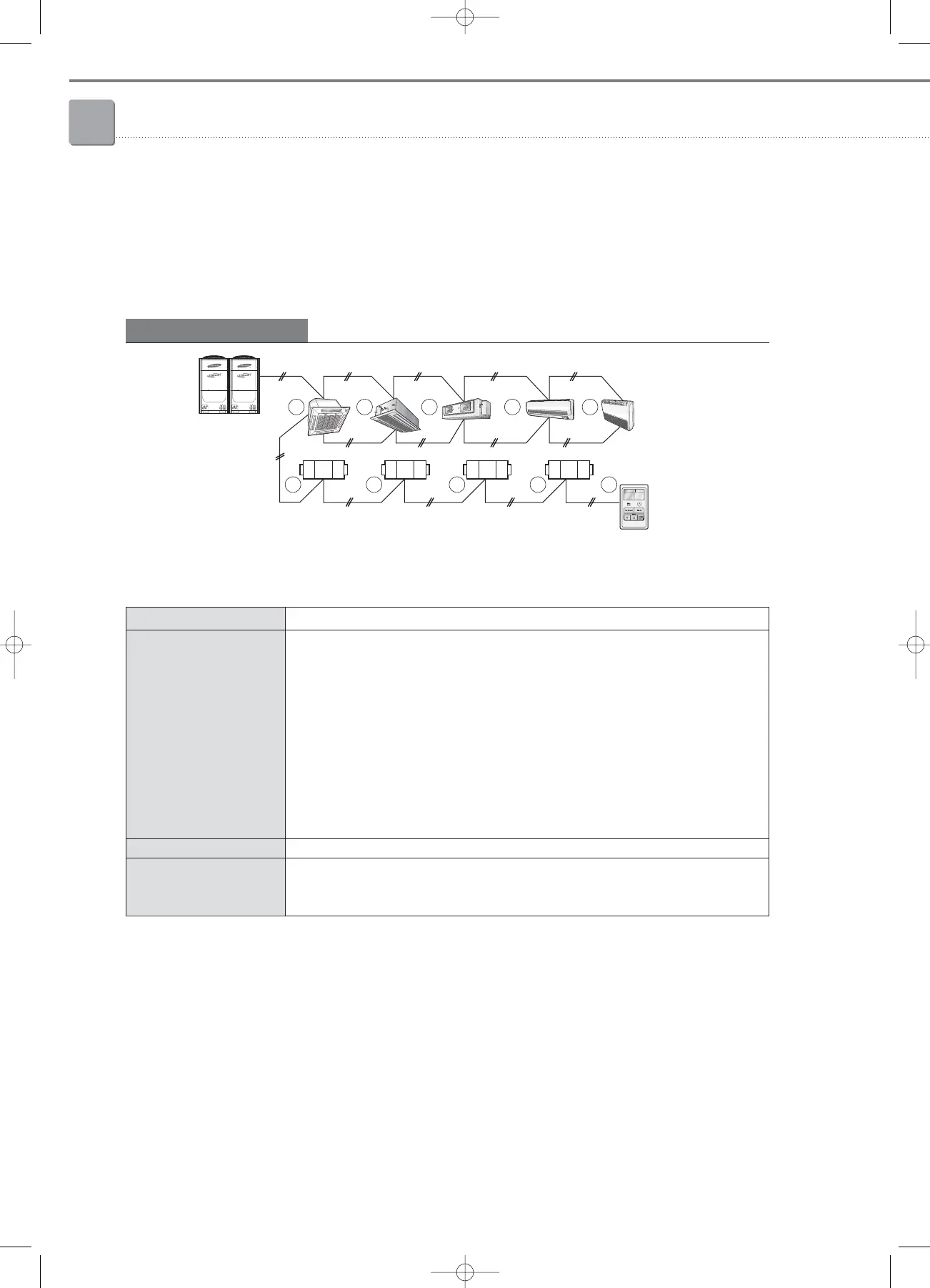
(5) Connection examples
Remote controller for indoor units (MWR-TH01, WS00, SH00) cannot be connected to the same COM2
communication line with the ERV remote controller.
The total number of indoor units and ERVs that can be connected to one ERV remote controller is Max.16.
DVM indoor unit synchronization
N : N : 1 Synchronous control
Outdoor unit
Wired R/C
COM1(F1/F2)
COM2
(F3/F4)
1 2 3 4 5
6 7 8 9 10
Connection Indoor unit : ERV : ERV remote controller = N : N : 1
If even only one indoor unit is turned on, all ERVs connected by the same COM2
communication line operate accordingly. If all indoor units are turned off, ERVs stop to operate.
At that time, it is possible to operate the connected ERVs only with a ERV remote controller.
ERV remote controller is not applicable for the indoor unit control.
Control Control example)
A. 1 Indoor unit is turned On among all indoor units
①
~
⑤➞
ERV
⑥
~
⑨
are automatically
turned On.
B. 1 Indoor unit is turned Off among all indoor units
①
~
⑤➞
No operation status change in all
ERV
⑥
~
⑨
.
C. All indoor units
①
~
⑤
are turned Off
➞
All ERV
⑥
~
⑨
are automatically turned Off.
D. Turn ERV remote controller
⑩
On
➞
Only ERV
⑥
~
⑨
are all turned On, no operation status
changes in indoor unit
①
~
⑤
.
Display Displays the operation status of one of connected ERV units on a random basis.
- When an error occurs in the indoor unit: Displays the indoor unit error code.
Error occurrence - When an error occurs in ERV: Displays the ERV error code.
- When errors occur in both indoor unit and ERV: Displays the error code with the higher value.
05-1_control systems(002~045) 3/15/08 4:09 Page 38
 Loading...


