EasyManua.ls Logo

Samsung DVM PLUS III - Page 584

Samsung DVM PLUS III
748 pages
To Next Page IconTo Next Page
To Previous Page IconTo Previous Page
Loading...
Control Systems
V-52
2
2
Centralized control system
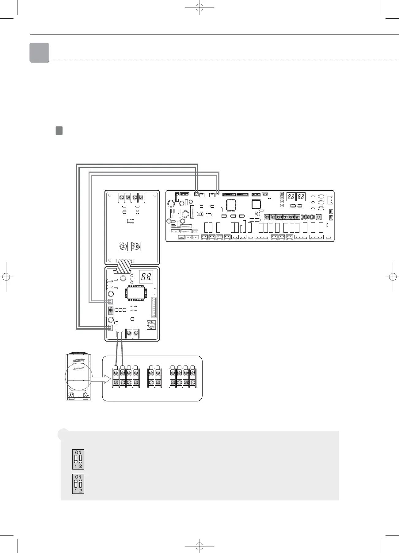
2-1. Interface module
(4) Installation
Connection between interface module and outdoor unit (example : DVM PLUS
III
)
WIRING
Setting the power setting switch
DC 12V, DC 5V together : All switches must be OFF (For DVM PLUS II, DVM PLUS III)
DC 12V only : All switches must be ON (For FJM, CAC, mini DVM)
Â
0
1
2
3
4
5
6
7
8
9
A
B
C
D
E
F
R2 R1 R2 R1
R1 R2
F1 F2 L R S T NN
OF1
OF2
5V CN13 (Black)
12V CN12 (Blue)
DC 12V
supply
DC 5V
supply
Outdoor unit PCB
SUB PCB
05-2_control systems(046~081) 3/6/08 14:02 Page 52

Table of Contents

Other manuals for Samsung DVM PLUS III

Related product manuals