❈ Display all indoor unit main addresses in rotation (for all indoor units with K2 to OFF)
Tracking completed
During trackingOutdoor unit detection
Control Systems
V-54
2
2
Centralized control system
➊
When interface module is connected to F1/F2 (Outdoor unit)
❷
When interface module is connected to R1/R2 (Centralized controller)
• Red : Red LED will be flickering when interface module communicates with CH 0 centralized controller.
• Green : Green LED will be flickering when interface module communicates with CH 1 centralized controller.
• Yellow : Yellow LED will be flickering when interface module communicates with CH 2 centralized controller.
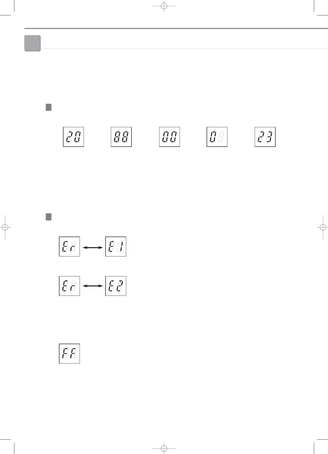
Operation display
Before outdoor unit
detection
➊
Communication error between outdoor unit
↔
Interface module
Error display
❷
Communication error between centralized controller
↔
Interface module
❈ When E1, E2 error occurs together, E1 is displayed first.
❸
Indoor unit communication checking
a. No indoor unit response
(during the normal communication mode after tracking process. Outdoor unit and interface module communicate normally)
b. All indoor units’ K2 switches are OFF (Centralized control disable status)
Software version after
power input (2.0)
➔➔➔➔
05-2_control systems(046~081) 3/6/08 14:02 Page 54