Control Systems
V-90
3
3
Integrated management system
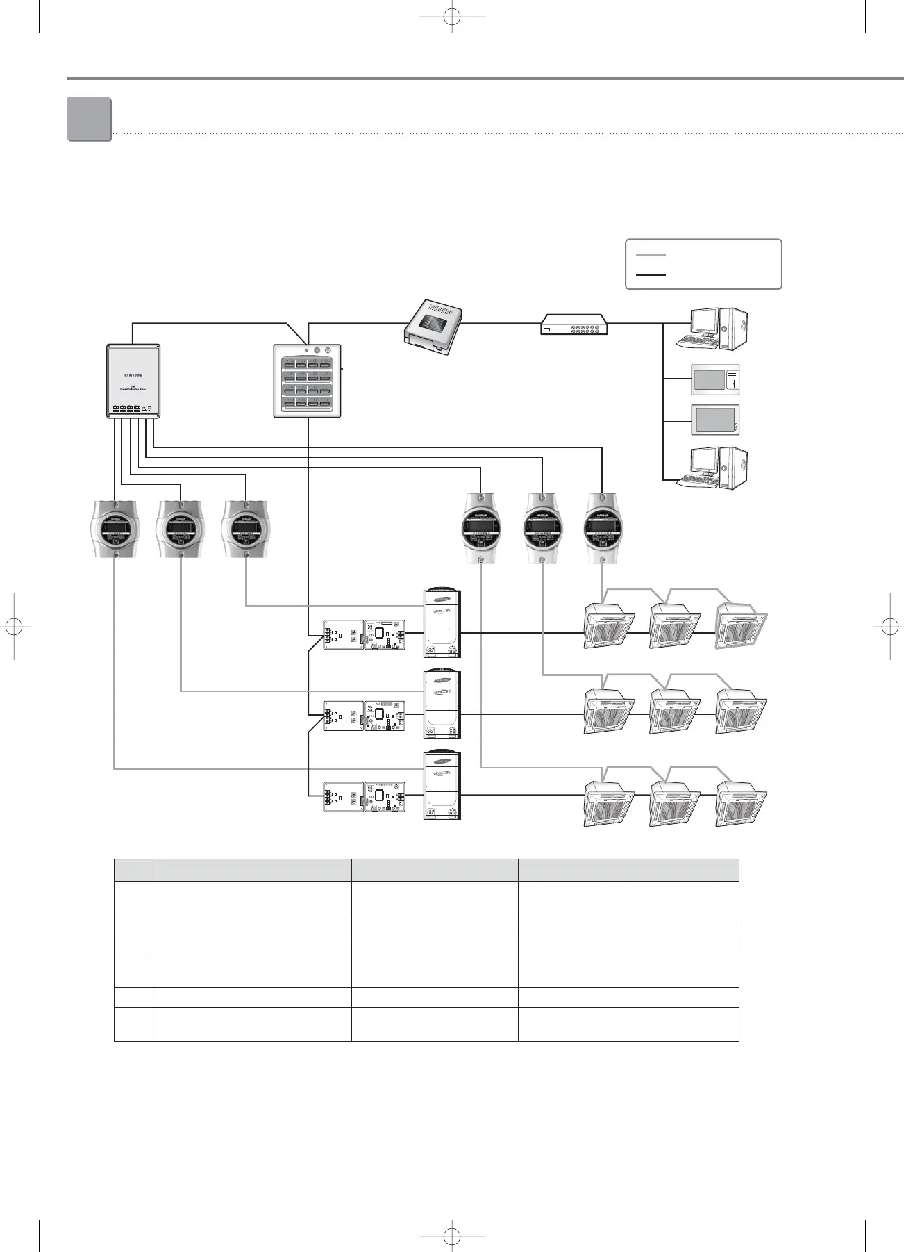
3-1. DMS (Data Management Server)
(8) DMS connection diagram
No Device Model Remark
1 Upper-layer device
S-NET3, S-NET i, S-NET mini, HUBs or network environment is required to
Web-Client support multiple upper-layer devices.
2 Centralized controller MCM-A202A
3 Interface module MIM-B04A, MIM-B13A
4 SiM
MIM-B12 Max. 8 watt-hour meters are supported
for 1 SiM.
5 Watt-hour meter Specified Korean products
6 Outdoor unit
DVM PLUS III , DVM PLUS II,
DVM PLUS, DVM, HR system,
C1-C2 wiring
MIM-D00
Ethernet Ethernet
Power supply
RS485
HUB
Watt-hour meter
R1-R2 Wiring
Power supply
Interface module
F1-F2 Wiring
Centralized controller
SiM
S-NET3
S-NET mini
S-NET i
Web Client
05-3_control systems(082~141) 3/6/08 14:04 Page 90