Installation
VI-6
1
1
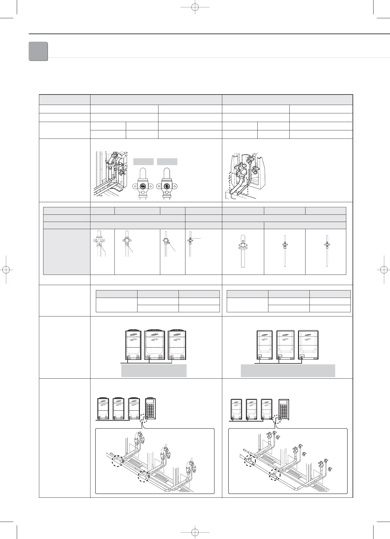
DVM PLUS III, DVM PLUS III HR
HP
Size (W x H x D)
14 HP, 16 HP8 HP, 10 HP, 12 HP
880 x 1703 x 765
240
242
320
323
1200 x 1703 x 765
Weight (kg)
Service valve
DVM PLUS III
DVM PLUS III HR
Outdoor unit
connection pipe size
Module installation
Outdoor joint
connection
DVM PLUS III, DVM PLUS III HR DVM PLUS II, DVM HR II
2HP, 14 HP8 HP, 10 HP
880 x 1646 x 765
250
260
330
-
1200 x 1646 x 765
DVM PLUS II
DVM HR II
1-1. Changes from DVM PLUS III concerned with installation
All digital units.
There is no arrange order.
Open
Gas Gas (High pressure) Liquid Oil balance
Ball type Angle type
Brazing Flare
Service valve
Type
Piping connection
Figure
❇ Ball valve with brazing type
• Outdoor joint kits must be installed horizontal
direction, even low pressure pipe.
8HP
(Digital unit)
14HP
(Digital unit)
10HP
(Digital unit)
• Open/Close
Port for
manifold
gauge
Close
Port for
manifold gauge
Port for
manifold
gauge
Port for
manifold
gauge
❇ Angle valve with flare & flange type
Gas Liquid Oil balance
Angle type
Flange Flare
HP Type Pipe size
16
Liquid pipe Ø12.70
Gas pipe Ø28.58
HP Type Pipe size
16
Liquid pipe Ø15.88
Gas pipe Ø28.58
A digital unit which is the largest
capacity should be placed at the end.
8HP
(Fixed unit)
14HP
(Digital unit)
10HP
(Fixed unit)
06_Installation(02~45) 3/15/08 4:34 Page 6