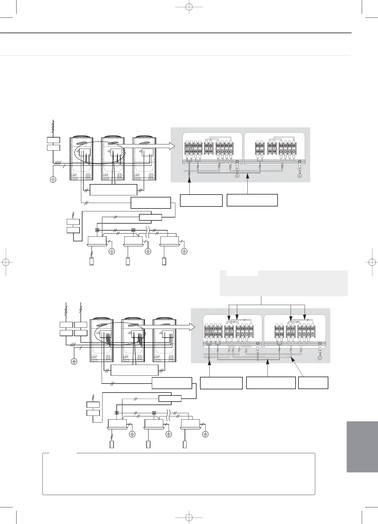
EasyManua.ls Logo

Samsung DVM PLUS III - Page 717

Samsung DVM PLUS III
748 pages
To Next Page IconTo Next Page
To Previous Page IconTo Previous Page
Loading...
VI-15
I
NSTALLATION
2) External connection diagram of DVM PLUS III HR
(1) 3 phase 4 wires
MCCB
MCU
ELB
MCCB
ELB
RSTN
OF1 OF2 OF1 OF2
RSTN
Communication cable
between the outdoor units
Communication cable
to MCU's
3 phase 4wires
(380~415V)
Earth
1 phase
2 wires
(220~240V)
Main unit
Main unit Sub unit
Sub unit 1 Sub unit 2
Earth
Wired
remote
controller
Earth Earth
Communication cable
between the outdoor units
Communication cable
from MCU's
(2) 3 phase 3 wires
Communication cable
between the outdoor units
Communication cable
to MCU's
MCCB
ELB
MCCB
ELB
MCCB
ELB
OF1 OF2
RSTN
OF1 OF2
RSTN
MCU
3 phase
3 wires
(380~415V)
1 phase
2 wires
(220~240V)
1 phase
2 wires
(220~240V)
Earth
Main unit Sub unit
Earth
Wired
remote
controller
Earth Earth
Communication cable
between the outdoor units
Communication cable
from MCU's
This line should be removed to protect it from a
short circuit.(Field wiring work)
CC
CC
aa
aa
uu
uu
tt
tt
ii
ii
oo
oo
nn
nn
All materials and methods of wiring work have to comply with local and national codes.
All field wiring work has to be provided by licensed electrician.
For safety and easy maintenance, we strongly recommend that each outdoor unit in module installation needs to
have its own MCCB and ELB.
;
NN
NN
oo
oo
tt
tt
ee
ee
Pull
box
Pull box
1 phase 2 wires
(220~240V)
06_Installation(02~45) 3/15/08 4:34 Page 15

Table of Contents

Other manuals for Samsung DVM PLUS III

Related product manuals