VI-39
I
NSTALLATION
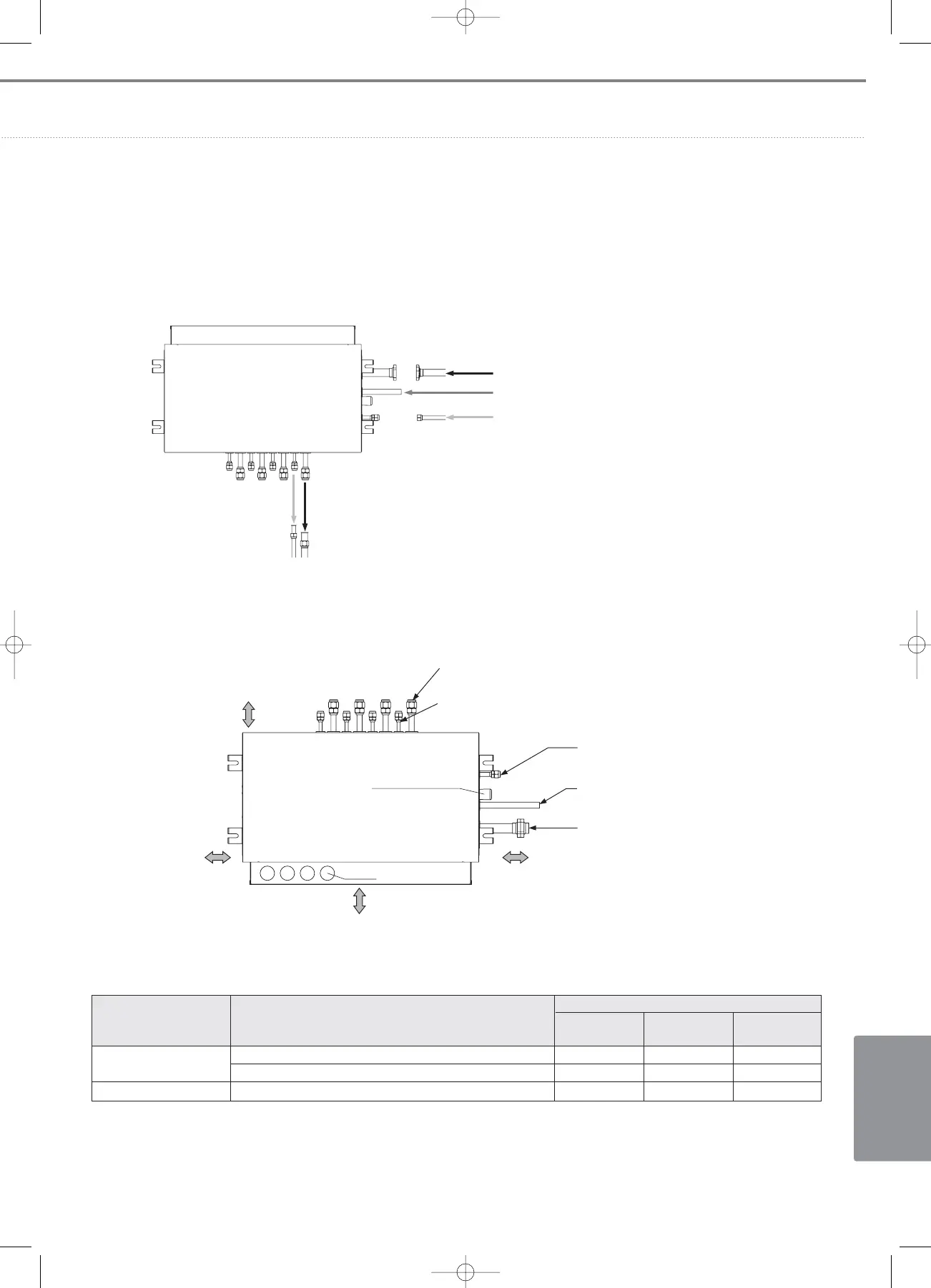
2) Connection of refrigerant pipes (Indoor/Outdoor)
From outdoor unit
Gas pipe connection (Flange)
High pressure gas pipe connection (Brazing)
Liquid pipe connection (Flare)
To indoor unit
Gas pipe to indoor unitLiquid pipe to indoor unit
3) Connection size of refrigerant pipes
4) Selection of pipe connection size
5/8”(15.88mm) : Gas pipe connection (Indoor unit)
3/8”(9.52mm) : Liquid pipe connection (Indoor unit)
Drain hole
(ID22.5/OD26.5)
1/2”(12.70mm) : Liquid pipe connection
(Outdoor unit)
3/4”(19.05mm) : High pressure gas pipe
connection (Outdoor unit)
300mm
(Inspection area)
300mm
(Inspection area)
300mm
(Inspection area)
300mm
(Inspection area)
Wire hole
1 1/8”(28.58mm) : Gas pipe connection
(Outdoor unit)
Pipe sizes between ~ Model (capacities)
MCU to indoor units
022 / 028 / 036 / 045 / 056 / 060 6.35 12.70 -
071 / 090 / 112 / 128 / 140 9.52 15.88 -
MCU to branch joints Total capacity of indoor unit connected downstream. Up to 12.70 Up to 28.58 Up to 22.23
Description
Liquid pipe
(mm)
Gas pipe
(mm)
High pressure
gas pipe (mm)
06_Installation(02~45) 3/15/08 4:34 Page 39
 Loading...


