S&C Instruction Sheet 461-504 71
Informational and Settings Screens
Definite Time 2 (check box). Select this check box to enable the Definite
Time 2 element. Note: This check box is not active unless the Definite
Time 1 element is enabled.
Denite Time 2 Current, A. Specify the current (in primary amperes) at which the
Denite Time 2 element picks up (minimum value: 5; maximum value: 6,300). Note: This
value must be greater than the Denite Time 1 Current setting, less than or equal to
the interrupting rating of the recloser, and smaller than the High Current Cutoff setting.
Denite Time 2 Time, s. Specify the time delay (in seconds) after which the Denite
Time 2 element trips (minimum value: 0; maximum value: 1,000). Note: This value must
be less than the Denite Time 1 Time setting.
NOTICE
In service center configuration software versions 1.6 and earlier, the MODE-
SELECTOR lever in the Down position or in R-NR mode would not go through
the reclosing sequence but would operate instantaneously in response to a
Trip event using the current setting set under the Initial Trip trip-operation
field on the TCC Curve Setting screen. (See the “TCC Settings Screen”
section on page 54.) The new NR Curve Settings screen allows the user to program
different TCC curves specifically for the MODE-SELECTOR lever when in NR or
R-NR mode.
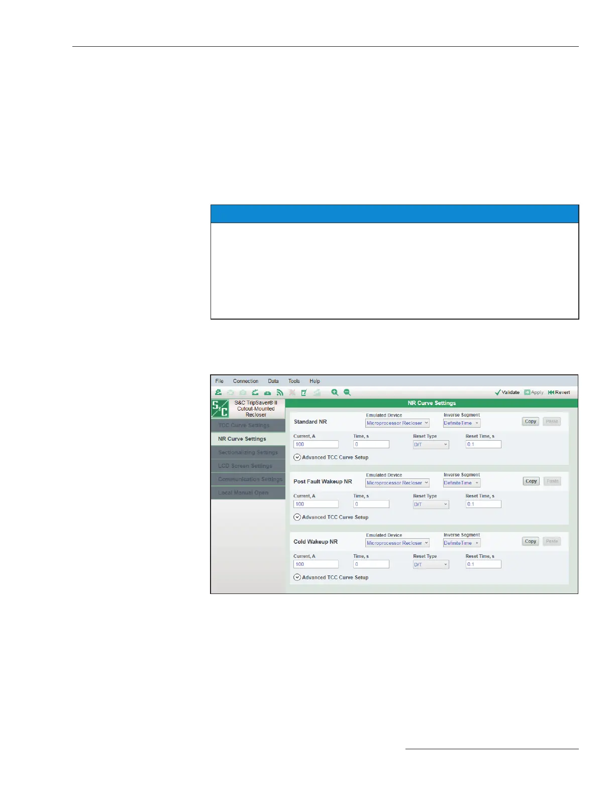
The NR Curve Settings screen is where the curves used by the TripSaver II recloser when
the MODE-SELECTOR lever is in the Down position or the recloser is in R-NR mode are
set. See Figure 102. All curves in the NR Curve Settings screen are set the same and have
the same setting ranges as the curves in the TCC Curve Settings screen.
NR Curve Settings
Screen
Figure 102. The NR Curve Settings screen.
 Loading...


