-22-
Mechanical disassembly flow chart
Mechanical disassembly should be made by following procedures chart.
Following steps show the basic procedures, therefore unnecessary step may
be ignored.
Caution:
The parts and screws should be placed exactly the same position as the origi-
nal otherwise it may cause loss of performance and product safety.
The wiring method of the leads and ferrite cores should be returned exactly the
same state as the original, otherwise it may cause lose of performance and
product safety.
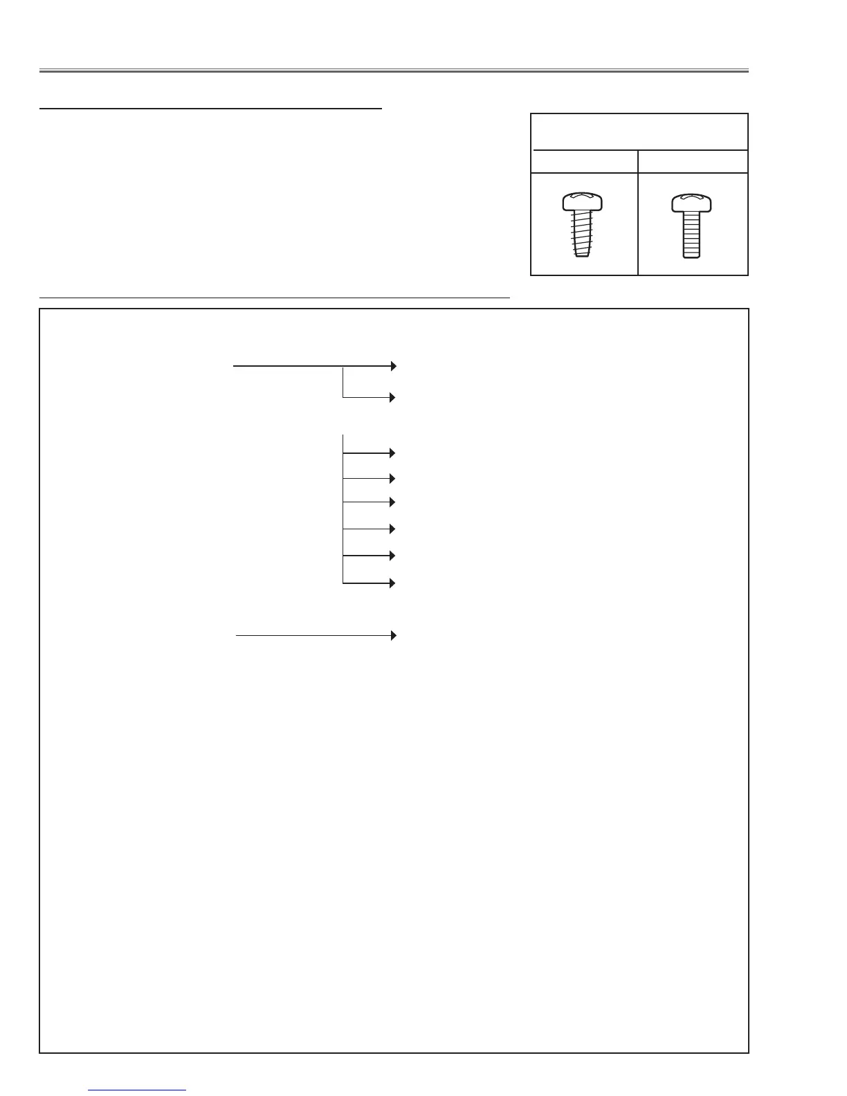
Screws Expression
(Type Diameter x Length) mm
T type M Type
Mechanical Disassembly
1 Cabinet front cover removal
2 Cabinet front removal 2-1 Lamp cover and PBS cover removal
2-2 LED board removal
3 AMC (Active Maintenance Cleaner) unit removal
3-1 AMC unit disassembly-1
3-2 AMC unit disassembly-2
3-3 AMC unit disassembly-3
3-4 AMC unit disassembly-4
3-5 AMC unit disassembly-5
3-6 Drive unit mounting
4 Main, RC rear board and Shutter removal
5 AV Panel assy removal 5-1 AV Panel assy disassembly-1
6 PFC-2 & Ballast-3/4 box removal
7 PFC-1 & Ballast-1/2 box removal
8 Power box assy removal
9 Lamp sign, Illumi sensor, Ex temp boards removal
10 Line filter assy removal
11 Rear fans assy removal
12 Lens shift assy, Motor and Lens net board removal
13 Lamps and ID IF boards and peripheral parts removal
14 Optical unit assy removal
15 Duct top removal
16 Fans removal
17 Handles removal
18 Cabinet bottom frame and stand legs removal
19 AMC unit rails and socket removal
Order of disassembly

 Loading...


