-74-
Electrical Adjustment
Circuit adjustments
CAUTION: The each circuit has been made by the fine adjustment at factory. Do not attempt to adjust the following
adjustments except requiring the readjustments in servicing otherwise it may cause loss of performance
and product safety. Before taking these adjustments, turn the projector for more than 10 minutes to sta-
bilize the operation.
WARNING : USE UV RADIATION EYE AND SKIN
PROTECTION DURING SERVICING.
CAUTION:
To prevent suffer of UV radiation, those adjustments
must be completed within 25 minutes.
[Adjustment Condition]
● Input signal
Computer signal ................. 0.7Vp-p/75W terminated (XGA)
Video signal ......................
1.0Vp-p/75W terminated (PAL/NTSC)
Component Video signal .... 1.0Vp-p/75W terminated (1080i/60)
● Image mode ........................
“Standard”
● Lamp mode.........................
“4-Lamps”
● Lamp control .......................
“Normal”
● Advanced color ...................
“Off”
● Auto picture control.............
“Off”
● Color management .............
“Off”
Note:
* Please refer to “Service Adjustment Menu Operation” for entering the service mode and adjusting the service
data.
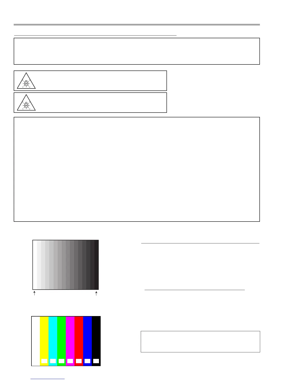
16 steps gray scale pattern
100% full color bar pattern
Equipment Digital voltmeter
Lamp mode 4-Lamps
Input AC Voltage 230V
Connect a digital voltmeter to test points and adjust the
volumes to be specified voltage as follow;
Test Points on PFC board Volume Voltage
K16B1 (+) K16B2 (-) VR1601 390Vdc
K16C1 (+) K16C2 (-) VR1651 390Vdc
Caution:
Be sure to connect the lamp when taking this adjust-
ment.
z Output voltage adjustment
● Test Pattern
This adjustment is not required even if the PFC board
is replaced because this adjustment is carried out be-
fore parts shipment.

 Loading...


