- 1 -
LCD PROJECTOR Model No. PLC-HF15000L
LENS REPLACEMENT AND INSTALLATION PROCEDURE
Be sure to consult with a qualified service personnel.
When installing or replacing the Projection
Lens, refer to this manual. For installation
of the lens, use the parts specified in this
manual.
Do not use the installation manual and
Light-Block Plates in the optional lens
package.
Check the following parts supplied to this
projector.
LENS INSTALLATION PRECAUTIONS
L
Lens installation and replacement should be made by a qualified service personnel.
L
Be sure to install the lens by following this procedure precisely.
L
Do not touch or remove any parts except the lens and related parts. It may result in
malfunctions, electrical shock, fire hazard or other accidents.
L
Before installing or replacing the lens, check that the Part No. of the Projection Lens
matches to the projector.
L
When moving or setting up the projector, be sure to replace the Lens Cover to protect
the surface. And be careful not to hold or subject the lens to strong forces. Otherwise
the lens, cabinet, or mechanical parts may damage.
L
For details of the lens and installation, contact the sales dealer where you purchased
the projector.
AVAILABLE LENS
Part No. Type Zoom Focus
LNS-W01Z Wide Fixed Lens Fixed Manual
LNS-W02Z Wide Zoom Lens Motor Driven Motor Driven
LNS-W03
LNS-W03E
On-Axis Wide Fixed Lens Fixed Manual
LNS-W04 Wide Zoom Lens Motor Driven Motor Driven
LNS-W06 Wide Zoom Lens Motor Driven Motor Driven
LNS-S03 Standard Zoom Lens I Motor Driven Motor Driven
LNS-S04 Standard Zoom Lens II Motor Driven Motor Driven
LNS-M02 Semi-Long Zoom Lens Motor Driven Motor Driven
LNS-T01
LNS-T01Z
Fixed Long Throw Lens Fixed Manual
LNS-T02
LNS-T02E
Long Zoom Lens Motor Driven Motor Driven
LNS-T03 Ultra-Long Zoom Lens Manual Manual
3 types of Light -Block Plates
Lens Attachment
3 types of Spacers
2 types of Safety Clamps
THE OPTIONAL LENSES BELOW ARE NOT APPLICABLE FOR PLC-HF15000L.
LENS PART NO. : LNS-W05, LNS-W07, LNS-S01, LNS-S01A, LNS-S02, LNS-S02Z, LNS-M01, LNS-M01E, LNS-M01Z
- 2 -
The installation procedure and needed parts for lens installation varies on Optional Lens. Check the Part No. of the
Optional Lens and be sure to install or replace the lens by following the procedure below.
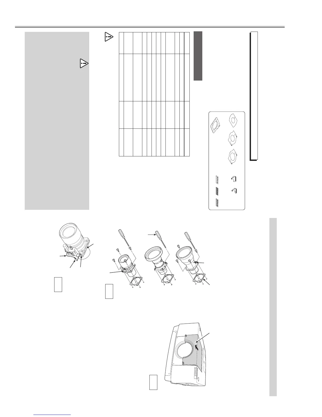
LENS REPLACEMENT AND INSTALLATION PROCEDURE
Fig. 3
3
Remove 2 Screws A. Slide the Top Cover
forward to take off. (See Fig. 3)
Focus Lens Lock Screw
Locate the Motor on right side.
Lens Attachment
Part No. (610 275 6029)
Connector
Lens Motor Lead
Fig. 2
Lens Attachment
Socket
1
Remove the safety lens cap on the front and
rear of the lens (mounting side). Insert the Lens
Attachment and secure with the four (4) screws
(supplied). (See Fig. 1)
Screw Driver
(supplied with the optional lens)
Fig. 1
Connect the Lens Motor Lead to the socket on
the top right of the Lens Attachment. (Motor
Driven Lens only) (See Fig. 2)
2
Turn off the projector, press the Main On/Off
Switch to Off and unplug the AC power cord
from the AC outlet.
A
A
Top Cover

 Loading...


