- 3 -
4
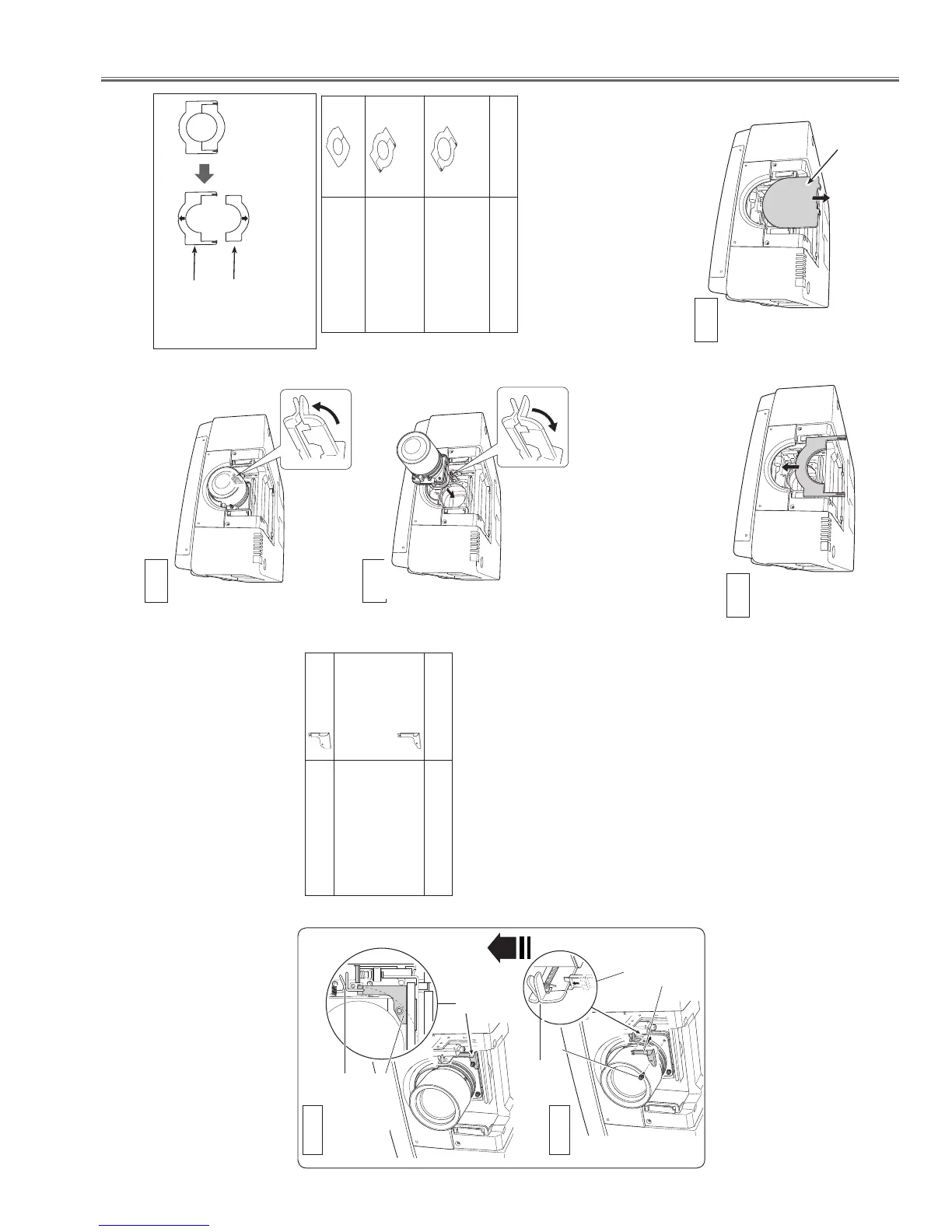
Remove the Cover Plate by lifting upwards.
(See Fig. 4)
5
This projector can use three (3) different types
of Light-Block Plates, use the Light-Block Plate
that corresponds to the appropriate optional
lens. (Refer to the list below.)
NOTE:
L
Make sure the shape of the Light-Block Plate is
correct.
L
Make sure the mark (UP/DOWN and FRONT/BACK)
on Light-Block Plates are correct and set them
properly.
L
Use two (2) Light-Block Plates for LNS-W03/LNS-W03E.
Light-Block Plate for each Lens
Light-Block Plate
Type No. (PART No.)
Lens Part No.
Type FK2A
(610 337 0064)
LNS-W01Z, LNS-W04,
LNS-W06, LNS-S03,
LNS-S04, LNS-M02,
LNS-T01, LNS-T01Z,
LNS-T03
Type FK2B
(610 337 0224)
LNS-W02Z, LNS-W03,
LNS-W03E, LNS-T02,
LNS-T02E
(610 335 4545) LNS-W03, LNS-W03E
6
Insert the lower Light-Block Plate. (See Fig. 5.)
7
Grasp (release lock) the Lens Lock Lever and
turn it fully upward. (See Fig. 6) Install the
Lens into the projector. Grasp the Lens Lock
Lever and turn the Lever fully downward until
lever is Locked (clicked position) properly. (See
Fig. 7) When installing the Motor Driven
Lens, be sure to mount Lens Motor on right
side. (See Fig. 1)
After installing the lens, make sure the lens is
not loose and properly installed.
Fig. 6
Fig. 7
LENS LOCK RELEASE
LENS LOCK
NOTE:
L
The Light-Block Plate FK2A and FK2B are separated
to the upper and lower plates.
Lower Plate
Upper Plate
DOWN
UP
Cover Plate
Fig. 4
Fig. 5
Grasp (unlock)
Lens Lock Lever
and pull upward.
Grasp (unlock)
Lens Lock Lever
and fully pull
downward until it is
locked (clicked).
- 4 -
Safety Clamp
Type No. (PART No.)
Lens Part No.
Type SC-A
(610 322 3759)
LNS-W01Z, LNS-W02Z,
LNS-W03, LNS-W03E,
LNS-W04, LNS-W06,
LNS-S03, LNS-S04,
LNS-M02, LNS-T01,
LNS-T01Z, LNS-T02,
LNS-T02E, LNS-T03,
Type SC-B
(610 322 3742)
NONE
1
Remove the screw holding the lens. (See Fig.8-1)
2
Insert the removed screw to the Safety Clamp.
3
Place the Safety Clamp in the location of the
removed screw. Make sure that the Safety
Clamp is mounted to hold the Lens Lock Lever
in the lock position. Check the placement of the
Safety Clamp. (See Fig. 8-2)
Set up the projector and project image on a
screen. Loosen the Focus Lens Lock Screw
and rotate the Projection Lens to obtain proper
focus. After adjusting focus, be sure to lock
the Projection Lens with the Focus Lens Lock
Screw securely. (See Fig. 1)
Adjust focus of the Projection Lens Part No.
LNS-W03 and LNS-W03E following the Focus
Adjustment on page 6.
8
Adjust focus of the Projection Lens. (LNS-W01Z,
LNS-W03 and LNS-W03E only.)
Safety Clamp
(SC-A)
Part No.
(610 322 3759)
Screw
Lens Lock Lever
Lens Lock Lever
Safety Clamp
Safety Clamp
Attached Figure
Fig. 8-1
Fig. 8-2
Safety Clamp
(SC-A)
Part No.
(610 322 3759)
9
To ensure that the lens is securely fixed to the
projector when mounting, be sure to attach the
provided Safety Clamp. There are two different
types of Safety Clamps depending on the lens
of the projector. Check the Part No. of the lens
before attaching the Safety Clamp and use a
Safety Clamp that matches to the lens.

 Loading...


