Section 2: Installation
Page 2-10 CG2 Series Operator Manual
2.5 CONNECTIONS
This section explains the power cable and interface cable connection procedures.
2.5.1 Standard interface connection
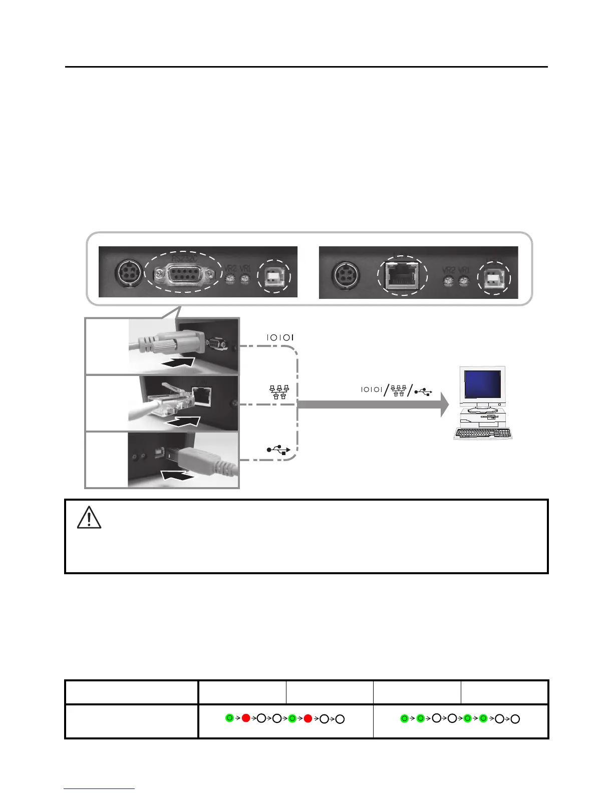
CG2 Series printers have two types of Main PCBs, and each type of PCB is equipped with a different type of
interface to perform data communication with the host. These are described as follows.
1) Type 1: USB and RS232C on-board
2) Type 2: USB and LAN on-board
Connect only one type of interface cable from the printer to the host computer. Use the cable that is
compatible with the standard of the interface board as stated in Section 7: Interface Specifications. Make
sure the cable is correctly oriented.
2.5.2 To activate the connected interface
After connection, you need to configure the printer to operate on the connected interface.
1. Please perform the procedures to set the appropriate interface mode as describe in Section 3.5
Operation Setting Mode.
2. In step 4 of this procedure, briefly press the FEED/LINE button repeatedly to select the interface mode
according to your connection.
Caution
Never connect or disconnect interface cables (or use a switch box) with power applied to either the host
or printer. This may caused damage to the interface circuitry in the printer/ host and is not covered by
warranty.
Connected Interface USB Wireless LAN RS-232C LAN
ON LINE (POWER)
indications
Type1: USB and RS232C on-board Type2: USB and LAN on-board
RS232C
LAN
USB
Host
Green –> Red (Blinks in turn)
flashes green in a long interval
 Loading...