Saia-Burgess Controls AG
Hardware manual for PCD3 series │ Document 26-789 ENG19│ 2018-06-29
Planning an application
Guidance
2-5
2
- If an application is mounted in a single row (max. 15 module holders), then
aftervePCD3.C100aPCD3.C200mustbeusedtoamplifythebussignal
(unlessthecongurationendswiththefthPCD3.C100orPCD3.C110).
- If the application is mounted in multiple rows, the restricted length of cable
means that only three module holders (1× PCD3.C200 and 2× PCD3.C100)
may be mounted in one row.
The following procedure is recommended to plan an application:
Select the I/O modules according to the requirements.
For digital PCD3 I/O modules, if possible use those with 16 connections,
these have one LED per digital I/O.
Calculate the required number of module carriers according to the number
of I/O modules. Check if the number of module carriers is permitted:
PCD3.Mxxxx 3020
3120
3160
3320
3330
3360
5xx0 6xx0
I/O bus connector for extensions No Yes
Number of inputs / outputs or
I/O module slots
64
1)
4
1023
1) 2)
64
1) When using digital I/O modules withPCD3.E16x or A46x with 16 I/Os each
2) The address 255 is reserved for the watchdog on all PCD3. The I/O reserved for the watchdog can not be used by
the user, and analog and H modules must not be deployed with the slots with base address 240
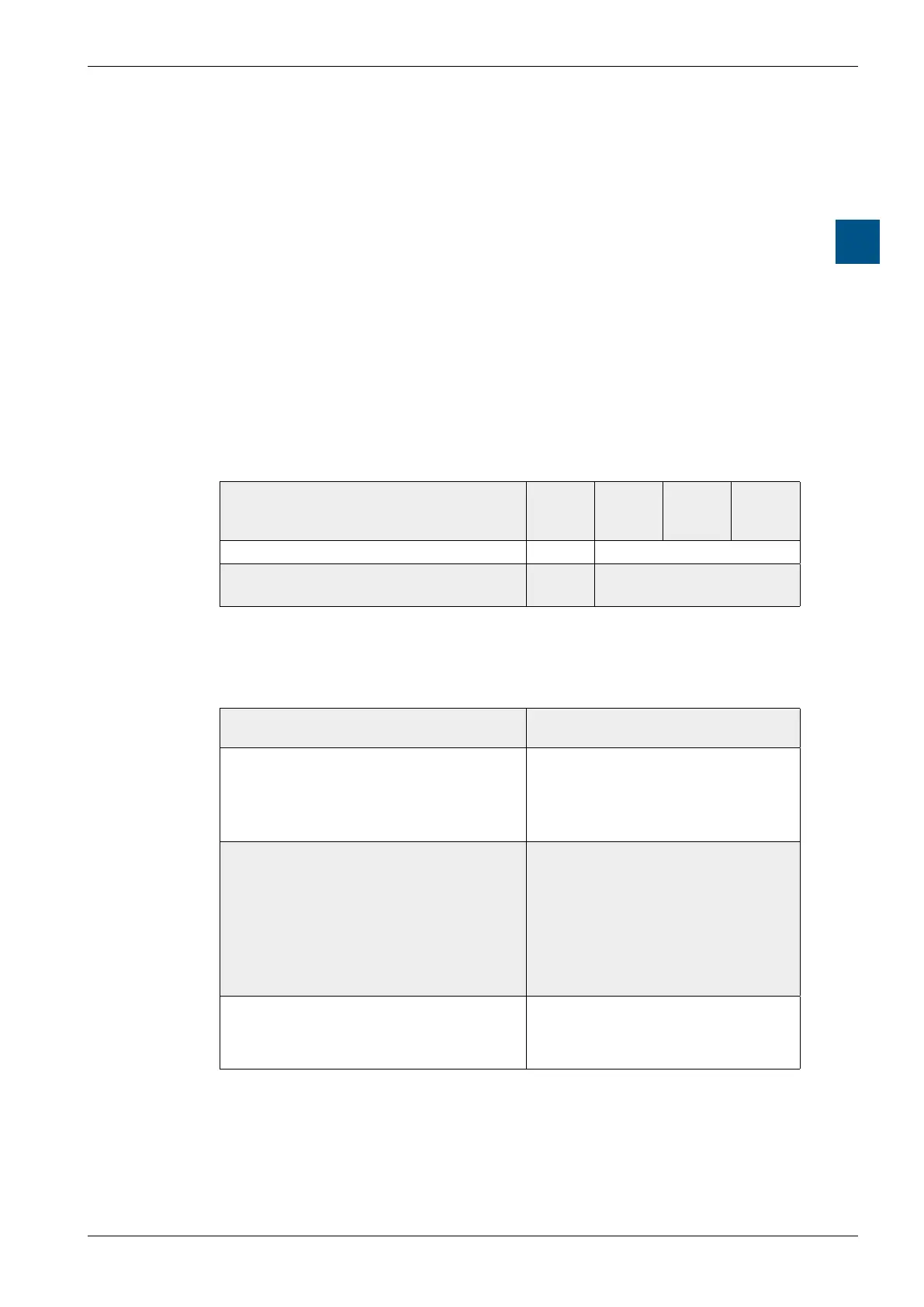
Arranging the module carrier in series according to the available mounting
surface and thereby determining the connection material:
Arrangement Required connection material
With a PCD3.Mxxx0, the LIOs in a
row max. 15 × PCD3.LIO's in series,
without extension cable, only with con-
nector PCD3.K010
n × PCD3.K010 connection plug
between PCD3 module carriers
With a PCD3.Mxxx0, the LIOs in sev-
eral rows.
Max. 3 PCD3.LIOs side by side and
one row below the other, with exten-
sion cables for the rows underneath
(max. 15 × PCD3.LIOs)
n × PCD3.K106/116 extension ca-
ble for connecting the last PCD3
modulecarrierofarowtotherst
PCD3 module carrier of the next
series.
n × PCD3.K010 connector be-
tween PCD3 module carriers.
Arranging a RIO node with the LIOs
side by side.
Max. 3 × PCD3.LIOs total
1…3 PCD3.K010 connector be-
tween PCD3 module carriers