Saia-Burgess Controls AG
Hardware manual for PCD3 series │ Document 26-789 ENG19│ 2018-06-29
Addressing
Guidance
2-11
2
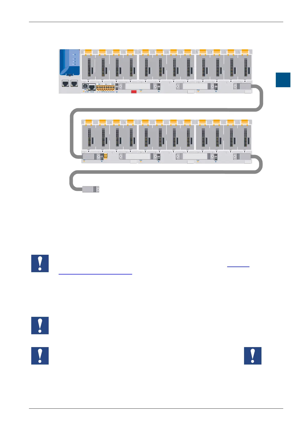
100
Saia PCD3.C
100
Saia PCD3.C
200
Saia PCD3.C
6860
ETH 2.1 ETH 2.2
Ethernet 2
USB
Saia PCD3.M
100
Saia PCD3.C
100
Saia PCD3.C
Extension cable
PCD3.K106
further series up to max. Address 1023
0 17616 1286432 48
192 368
Theaddressoftherstmoduleinasecondorthirdseriesisdeterminedbythe
address of the last module in the previous series +16.
For easier wiring, the module slots of the PCD3 module carriers are labeled with
the numbers 0 to 3. For more precise addressing, each module carrier and also
eachmoduleadditionallyhasanaddresseldinthelowerrightcornerofthe
housing.Howtheseaddresseldsareusedisdescribedin the next chapter.
Address 255 is reserved for the watchdog relay. Modules using this address must
not be inserted in module slot 16. For additional details, please see chapter
3.15.3 Hardware watchdog.
EachadditionalmodulecarrierPCD3.C100/C200oersspacefor4additional
I/O modules, at the end of the bus a PCD3.C110 provides space for 2 additional
I/O modules. The connection to the next series is made via the 26-wire extension
cable PCD3.K106 / K116.
Forces that occur at too small radii of the cable (smaller than the natural radius,
so buckling), can cause damage to the connector!
The extension cables must not be connected or disconnected while the
controller is under voltage!