Saia-Burgess Controls AG
Hardware manual for PCD3 series │ Document 26-789 ENG19│ 2018-06-29
Connections on orange terminal block
PCD3.Mxxx0 Classic CPU and expansion enclosure
3-42
3
Restrictions
Since the address 255 is in the normal I/O range, there are restrictions regarding
the permissible I/O modules in certain slots:
Typo Restrictions
PCD3.Mxxx0 1. No analog, counting and positioning modules in the slot with
base address 240 (except PCD3.W3x5, PCD3.W6x5 and
PCD3.W800,thesearenotinuencedbythewatchdog)
2. Output 255 can not be used for digital I/O modules either
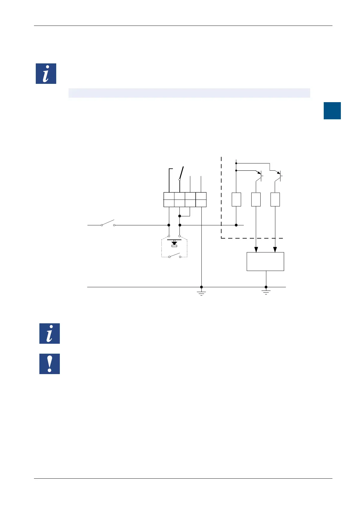
Watchdog - connection scheme
WD
+24V
0V
5 6
7
8
0
1+
PCD3
+24V GND
WD WD
Supply
Start
Bridging switch
for
CPU-Start
Process
Main switch
A-Modul
1) Switching power of the Watchdog contact: 1 A, 48 VAC/DC
The status of the watchdog relay can be read in via I 8107.
Status: 1 = watchdog relay energized (Not with power CPUs).
WiththePowerCPUPCD3.Mxx60asofrmwareversion1.28.xx,thestatusof
the watchdog relay can be read via media mapping.