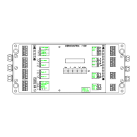
Connectors and Interfaces VC 1100
Version 2 → connect/VC1100E
3-2 C01 / C02 - C11 / C12 © Schenck VIBRO GmbH, D-64273 Darmstadt, November 97
Inputs: Terminal: Page:
Relay 1 10 ... 12 7
Relay 2 13 ... 15 7
Relay 3 16 ... 18 7
OK-Relay 7 ... 9 7
Analog Output 1 Channel A 3 ... 4 9
Analog Output 2 Channel B 5 ... 6 9
Buffered Output Channel A 31 ... 32 10
Buffered Output Channel B 33 ... 34 10
Remote I/O:
RS-232-C IN 25 ... 30 11
RS-232-C OUT C 28 ... 30 11
Die Anschlüsse im Einzelnen:
Symbols
Folgende Abkürzungen werden verwendet:
TE = Technical Earth (Ground)
SE = Shield Earth (Ground)
PE = Protective Earth (Ground)
↓ = General Symbol for Reference Level
0VA = Analog Circuits
0VD = Digital Circuits
L = Line Voltage
N = Neutral
DC = Direct Current/Voltage
AC = Alternating Current/Voltage
TD = Transmit Data (RS-232-C)
RD = Receive Data (RS-232-C)
SG = Signal Ground (RS-232-C)
BA = Buffered Output Channel A
BB = Buffered Output Channel B
TE (0VA) and 0VD can be connected at a central point.