VC 1100 Connectors and Interfaces
VC1100E/connect Version 2 →
© Schenck VIBRO GmbH, D-64273 Darmstadt, November 97 C01 / C02 - C11 / C12 3-7
Outputs
Relays
Consider the following if the relay outputs are to be used.
♦ Decide if the relays are to be "normally energized" or "nor-
mally de-energized". Setup parameters (N10, N11, N12)
must be consistent with the wiring.
Refer to the examples on the next page.
♦ If a relay is configured as latching (see parameters N07, N08,
N09) there are three ways to reset it.
With the operating panel; via the remote interface; using the
Relay-Reset Input
To use the Relay-Reset Input, connect a galvanically free
switch to terminals 35 and 36 (see previous page).
♦ If conductive loads are connected, provide appropriate spark
suppression placed as close as possible to the part that would
generate the spark.
Contact Rating: max. 5 A, 220 V AC (Ohmic load)
A spark extinguisher must be installed as close to the
spark generator as possible !
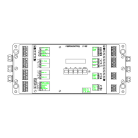
Fig. 3 - 5 : Connecting the-Relays
Figure 3 - 5 shows the contacts in the de-energized position.