Do you have a question about the Schenck Vibrocontrol 110 C01 and is the answer not in the manual?
Specifies supply voltage requirements and power consumption for different models.
Details the fuse types and protection mechanisms used in the device.
Highlights critical safety instructions for installation and operation.
Introduces the service mode for advanced functions and diagnostics.
Guides on testing relay activation and status within the service mode.
Explains how to test analog output voltages and currents.
Describes the self-test procedure for checking system modules.
Details the self-calibration function for the device.
Introduces the error message system and its display.
Lists and explains unit-specific error codes and their meanings.
Lists and explains error codes related to communication issues.
Provides guidance on responding to different types of error messages.
Covers enabling/disabling monitoring functions and setting limit values.
Details how to configure relay assignments and logic for alarm events.
Explains the self-monitoring routine for pickups and cables.
Describes service functions for testing relays, outputs, and system diagnostics.
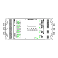
Provides instructions for mounting the unit and connecting transducers and wiring.
Outlines steps for checking wiring, supply voltage, and parameters after installation.
Details how to use service functions to verify connected peripherals and functions.
| Model | Vibrocontrol 110 C01 |
|---|---|
| Output Signal | 4-20 mA |
| Power Supply | 24 V DC |
| Protection Class | IP65 |
| Type | Vibration Monitor |
| Frequency Range | 10 - 1000 Hz |
| Accuracy | ±5% |
| Operating Temperature | -20°C to +70°C |