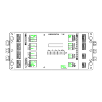
VC 1100 Connectors and Interfaces
VC1100E/connect Version 2 →
© Schenck VIBRO GmbH, D-64273 Darmstadt, November 97 C01 / C02 - C11 / C12 3-9
Analog Outputs
The analog outputs are used for example with strip chart recorders
and analog meters. These analog outputs are not galvanically
free, (isolated) and should only be used with instruments that have
galvanically free inputs.
Both analog outputs are independent and of equal design.
Their function depends on how they are configured (see parame-
ters L1, L2, L3, L4).
Example :
Configure analog output 1 for the measured vibration value of
channel B "vib_B" using a 4 ... 20 mA signal.
The setup parameters for channel B are:
− Measured Parameter J04: v (vibration velocity)
− Unit J06: mm/s (or ips)s
− Signal Detection J08: rms
− Measured Tange J10: 50.0 (or 2.00)
Using this setup, an output signal of 4 mA corresponds to a vibrat-
ion level of 0 mm/s (0 ips). An output signal of 20 mA corresponds
to a vibration level of 50.0 mm/s (2.00 ips).
Technical Data :
Current Output: 0/4 ... 20 mA Load < 500 Ω
Voltage Output: 0 ... 10 V R
L
> 1 kΩ, short-circuit proof
Fig. 3 - 7: Connecting Analog Outputs