Installation manual
HB-37420-810-01-25F-EN PSC1-C-100 Installation manual - V2.2.docx Page 101 of 201
Version: 25F
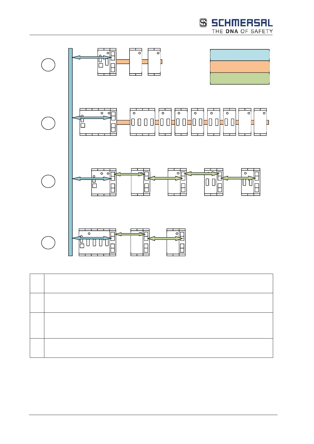
5.5.1 Schematic diagram of the network topology
1 Communication of a PSC1 compact with
• Central expansion modules via SDDC CAN backplane bus
• SMMC
(1)
via Ethernet
2 Communication of a PSC1 modular with
• Central expansion modules via SDDC CAN backplane bus
• SMMC
(1)
via Ethernet
3 Communication of a PSC1 modular with
• Decentral expansion modules via SDDC Ethernet
• SMMC
(1)
via Ethernet
• A switch is required in the configuration shown
4 Communication of a PSC1 compact with
• Decentral expansion modules via SDDC Ethernet
• SMMC
(1)
via Ethernet
Options:
(1)
SMMC on request
SDDC CAN (central)
SMMC
(1)
SDDC ETH (decentral)