Installation manual
HB-37420-810-01-25F-EN PSC1-C-100 Installation manual - V2.2.docx Page 77 of 201
Version: 25F
4.3.4 Digital outputs
The modules
• PSC1-C-100
• PSC1-E-131-..., PSC1-E-133-..., PSC1-E-37-...
each have identical outputs.
The PSC1 series provides different types of outputs that can be connected together
either separately or in groups.
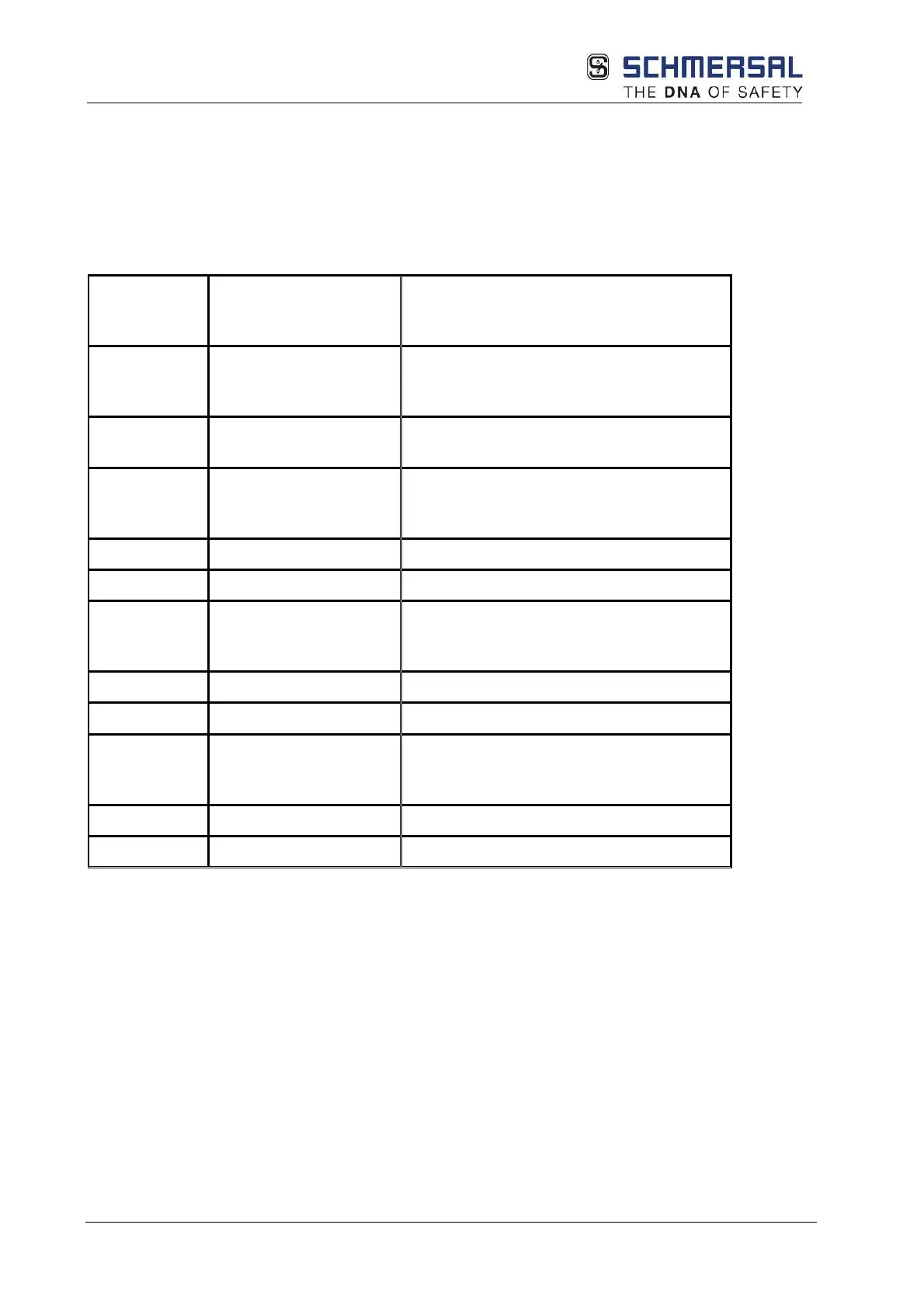
Output Architecture
according to EN ISO
Remark
Combination
of 2 relays Q4
– Q5
4 Complete shutdown channel
corresponding to architecture category 4
according to EN ISO 13849-1
Q4,Q5,
Not safe Only functional
Q0 _P and
Q1_N
4 Complete shutdown channel
corresponding to architecture category 4
according to EN ISO 13849-1
Q0_P
Not safe
Only functional
Q1_N
Not safe
Only functional
Q2_P and
Q3_N
4 Complete shutdown channel
corresponding to architecture category 4
according to EN ISO 13849
Q0 – Q3 4 Complete shutdown channel
corresponding to architecture category 4
according to EN ISO 13849-1
Y0
Not safe
Signal output
Y1
Not safe
Signal output
The Qx_P, Qx_N and Qx outputs are subjected to a plausibility test in all operating states. In the
switched on state, all outputs are tested for correct function using a cyclic test pulse. For this
purpose the output is switched to the corresponding inverse value for a test duration TT < 300
µs as a maximum, i.e. a P output is briefly switched to 0 VDC potential and an M output is
briefly switched to 24 VDC potential.
The relay outputs are monitored for plausibility during each switching operation. The relay
outputs must be switched cyclically and therefore tested to retain the safety function. The
switching/test cycle is to be defined dependent on the application.