Installation manual
HB-37420-810-01-25F-EN PSC1-C-100 Installation manual - V2.2.docx Page 16 of 201
Version: 25F
3.7 Device characteristic data
3.7.1 Basic modules
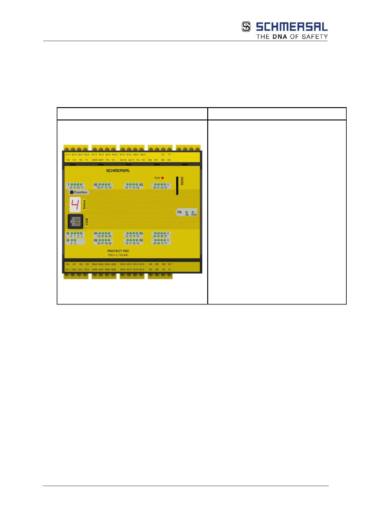
3.7.1.1 PSC1-C-100 (-FBx
(1)
) (-MC)
Version of the module with following
peripherals:
14 digital inputs
2 pulse outputs
20 digital I/Os
2 relay outputs (1-channel)
2/4 pn or pp switching outputs
6 signal outputs
1 diagnostics and configuration
interface
1 function button
1 7-segment display
1 status LED
14 status LEDs for inputs
6 status LEDs for signal outputs
2 status LEDs for relay outputs
4 status LEDs for outputs
20 status LEDs for I/Os
1 optional: Communication interface
incl. memory card slot (-FBx
(1)
)
1 optional: Memory card slot
Properties of the module:
• Can be expanded to:
o Max. 126 safe digital inputs,
o Max. 36 safe digital outputs,
o Max. 100 safe digital I/O,
o Max. 17 safe relay outputs (2-channel),
o Max. 38 signal outputs
o And/or 12 safe axes
• Logic processing up to PL e according to EN ISO 13849-1 or SIL 3 according to IEC
61508
• Freely programmable modular controller for up to 3000 IL instructions
• Function plan-orientated programming
• Pulse outputs for cross-circuit detection on digital input signals
• External contact monitoring on switchgear connected (EMU)
• Monitored relay outputs for safety-related functions
• Switchable safe outputs pn, pp switching for safety-related functions
• Complete speed and position-related safety functions for drive monitoring as per IEC
61800-5-2 integrated into firmware
o Three-dimensional functions for safe speed and range monitoring possible