Installation manual
HB-37420-810-01-25F-EN PSC1-C-100 Installation manual - V2.2.docx Page 122 of 201
Version: 25F
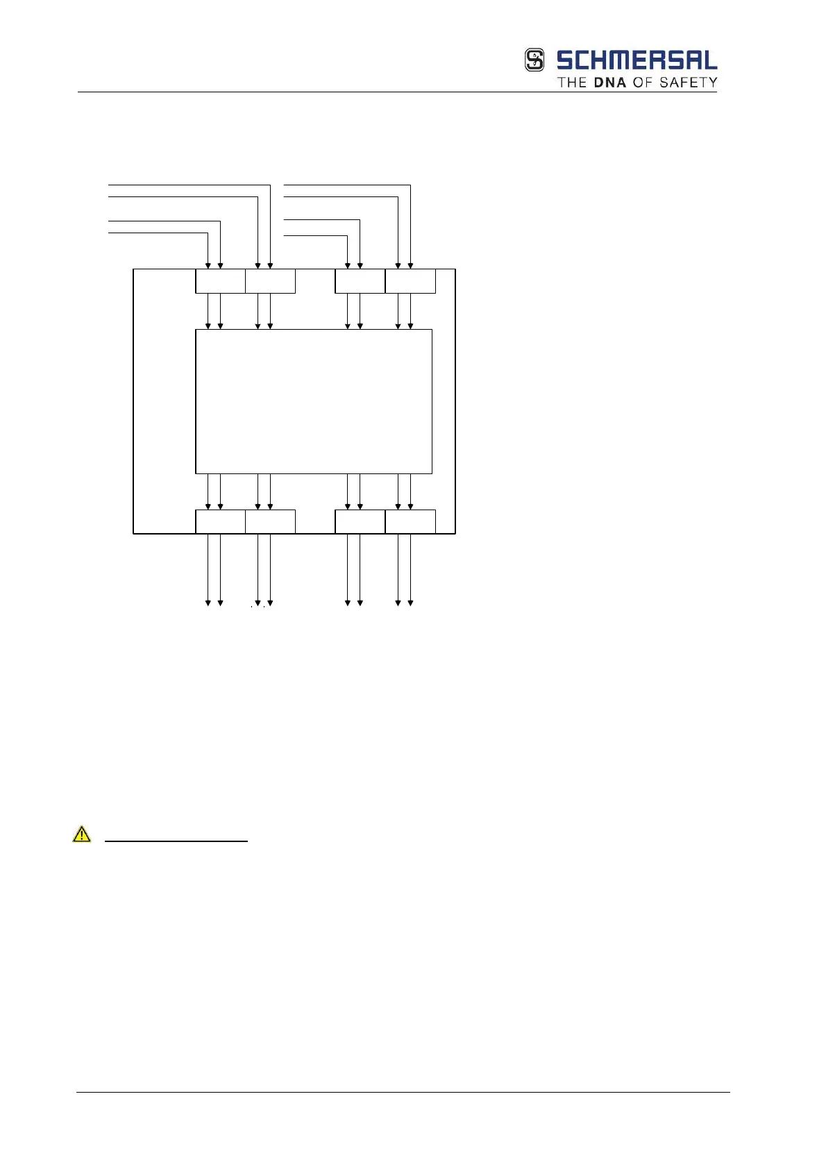
5.9 Connection of the external encoder supply
5.9.1 Incremental, HTL, SIN/COS, SSI
1)
PSC1
Spannungs-
überwachung
der externen
Geber-
versorgungs-
spannungen
X15
1
2
UE1+
UE1-
X1
UE1+
UE1-
9
2
UE3+
UE3-
X3
UE3+
UE3-
9
2
UE2+
UE2-
X2
UE2+
UE2-
9
2
UE4+
UE4-
X4
UE4+
UE4-
9
2
X13
1
2
X17
1
2
X15
1
2
X19
1
2
1)
1)
2)
2)
3)
3)
Options:
(1)
Only PSC1-E-22 and PSC1-E-24
(2)
Only PSC1-E-23 and PSC1-E-24
(3)
Only PSC1-E-24
The PSC1 module supports encoder voltages of 5 V, 8 V, 10 V, 12 V and 24 V that are
monitored internally as per the configuration selected.
If an encoder system is not supplied via the PSC1 module, a supply of power must still be
connected to terminal X13 and X15 and configured appropriately.
The encoder supply must be protected with maximum 2 A.
Safety instructions:
• The GND connection for the encoder must be connected to GND on the PSC1