Installation manual
HB-37420-810-01-25F-EN PSC1-C-100 Installation manual - V2.2.docx Page 56 of 201
Version: 25F
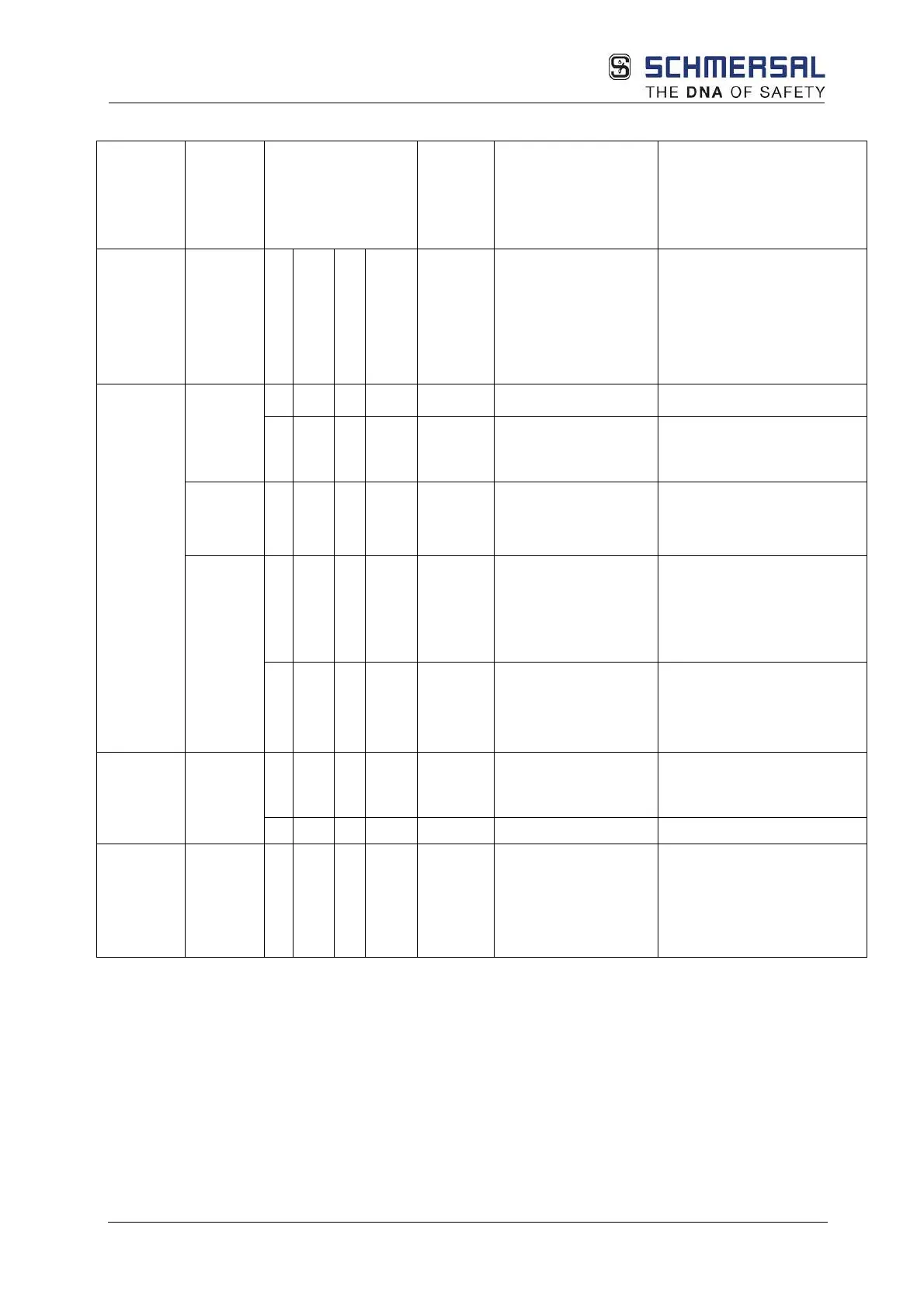
4.2.1.5 Overview of achievable PL for digital safety inputs
Type of
sensor /
input
element
Input Tests that can be
configured /
operative tests
Achieva
ble PL
accordi
ng to
EN ISO
Fault exclusion for
input element
Condition for input
element
Cross-circuit test
With time
Start test
Cyclic test in
operation
Single-
channel
I00..I13
b
Input element proven in
operation
O O d
All faults on the input
element
Short-circuit on the
input/signal wire
MTTF
d
= high
Connection in the switch
cabinet or protected laying
I00..I04
I08..I13
e
All faults on the input
element
Short-circuit on the
input/signal wire
Input element corresponds at
least to Plr
Connection in the switch
cabinet or protected laying
All
X d
Stuck
Short-circuit on the
input/signal wire
Predominantly high level
required (T
High
> 100 * T
Low
).
Positive opening,
MTTF
d
= high
Connection in the switch
cabinet or protected laying
X O O e
All faults on the input
element
Short-circuit on the
input/signal wire
Input element corresponds at
least to Plr
Connection in the switch
cabinet or protected laying
MTTF
d
= high
Two-
channel
parallel
All
d
Short-circuit between
input/signal wire
Connection in the switch
cabinet or protected laying
MTTF
d
= medium
X
e
MTTF
d
= high
Two-
channel
parallel
All
X
e
Short-circuit between
input/signal wire (only
with same switching
elements = 2xNO or
2xNC)
Connection in the switch
cabinet or protected laying
MTTF
d
= high
Options:
X:
Diagnostic measure activated
O:
At least 1 diagnostic measure activated