Installation manual
HB-37420-810-01-25F-EN PSC1-C-100 Installation manual - V2.2.docx Page 151 of 201
Version: 25F
7 Commissioning
7.1 Procedure
Commissioning is only allowed to be undertaken by qualified personnel!
Please follow the safety instructions during commissioning!
7.2 Sequences for switching on
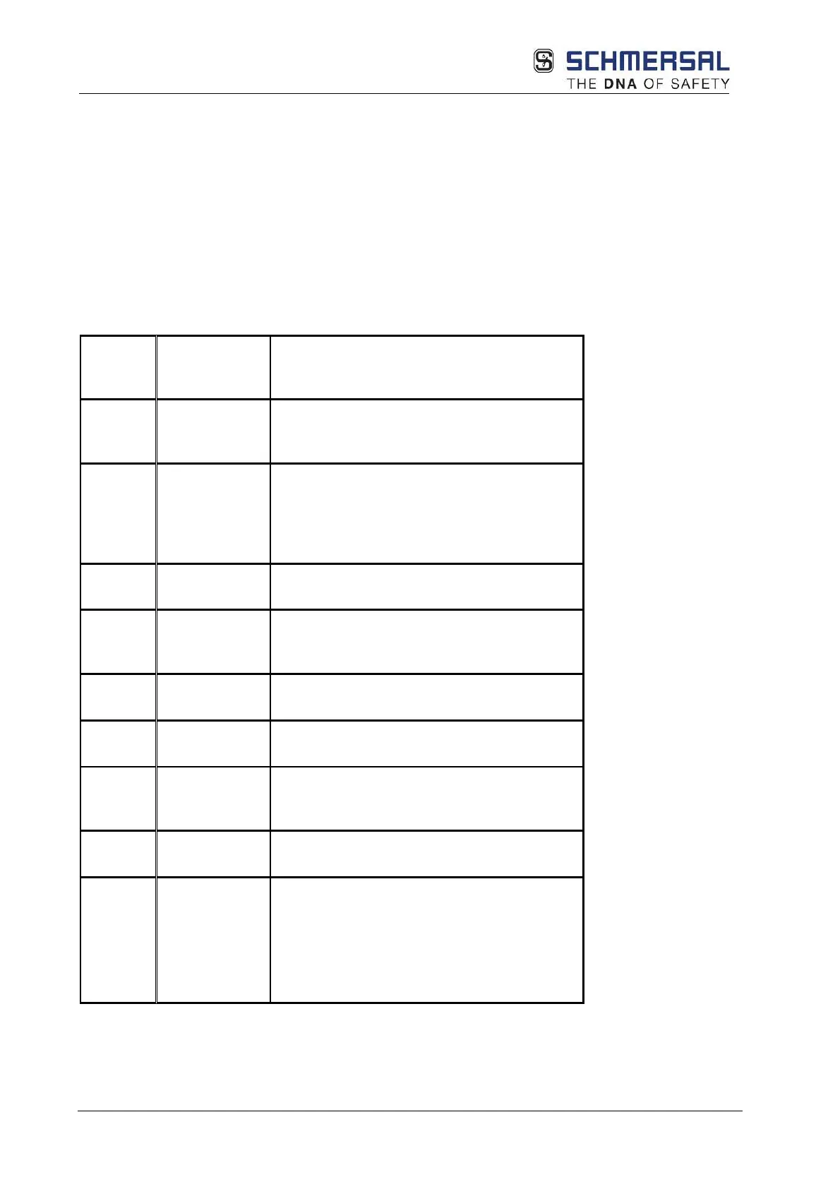
Each time after restarting the module, if there are no errors, the following phases are run
through and displayed on the seven-segment display on the front:
7-
segment
display
Mode Description
"1" STARTUP
Synchronisation between both processor
systems and checking the
configuration/firmware data
"2" SENDCONFIG
Distribution of the configuration/firmware
data
and further checking of these data.
Subsequent
range calculation for the configuration data.
"3"
STARTUP
If present, initialisation of a bus system
"4" RUN
Normal operation of the system. All outputs
are switched based on the actual state of
the logic.
"5" STOP
Parameter data and program data can be
loaded externally in the stop mode.
"A" ALARM
Alarm can be reset via digital input or reset
"E"
ECS alarm
ICS alarm
ECS alarm can be reset via digital inputs or
reset button on the front.
"F"
Fault
Faults can only be reset via module
ON/OFF.
"."
PROFIsafe
status
Slave F bus (PROFIsafe/FSoE):
Off: F bus not used Slow flashing F bus
configured, no connection to the master
Fast flashing:
Connection to the master, F bus activation
pending
On: F bus connected