Installation manual
HB-37420-810-01-25F-EN PSC1-C-100 Installation manual - V2.2.docx Page 76 of 201
Version: 25F
4.3.3 Permissible capacitive and inductive load on safe outputs
The safe outputs on the PSC1 are of an OSSD character. I.e. the outputs are shut down
cyclically to test the shutdown capability and the status read back.
The test on the shutdown capability is undertaken based on the following criteria / functions:
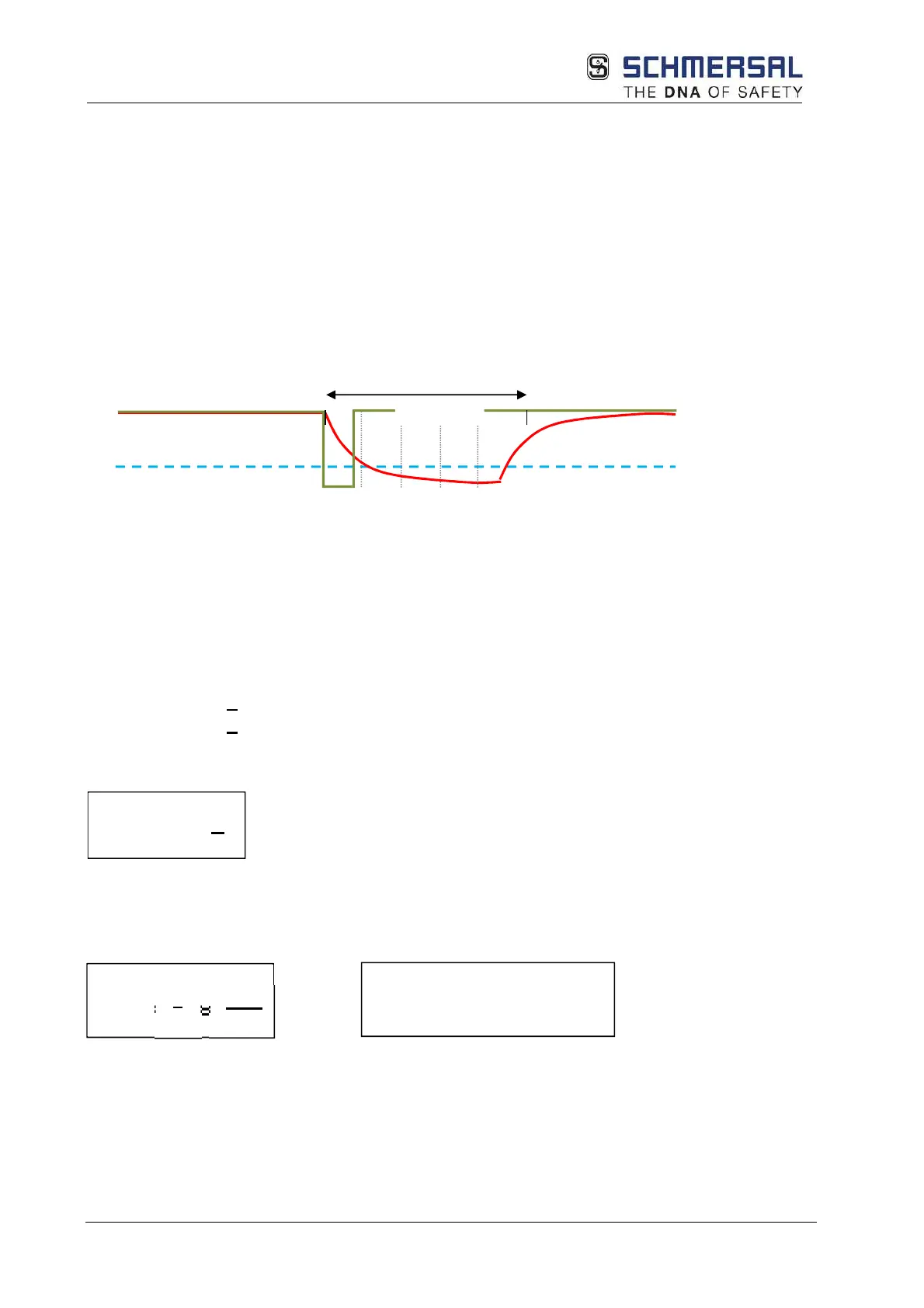
- After the shutdown of the output, the output voltage is allowed to be max. 5.6 V
- The permissible voltage must be reached at the latest after 400 µs
- If the permissible voltage is reached, the test is considered successful, the output is re-
activated without any further delay
- If the permissible voltage has still not been reached after 400 µs, an alarm is triggered
and all safe outputs (second channel for safe outputs!) are deactivated
The illustration below shows the ideal (green) and typical (red) curves.
To determine the maximum permissible capacitance or inductance, the time constant τ of the
actual RC or RL element on the output is to be considered.
This RC or RL element defines the actual discharge curve:
The voltage of max. 5.6 V is reliably achieved after 3 τ.
Therefore:
3
τ
< 350µs
τ
< 100µs
With the relationship
The max. capacitive or inductive load that can be used in conjunction with the related
ohmic load can be determined:
or
Typical values for the capacitance C are C=20 nF and for the series inductance L = 100 mH
τ
= RC =
L
Ideal curve
Actual curve
Switching threshold
τ 2τ 3τ 4τ
Max. 400 µs
L
max
=
τ
* R = 10
-4
* R
C
max
= =
R
10
R