Installation manual
HB-37420-810-01-25F-EN PSC1-C-100 Installation manual - V2.2.docx Page 105 of 201
Version: 25F
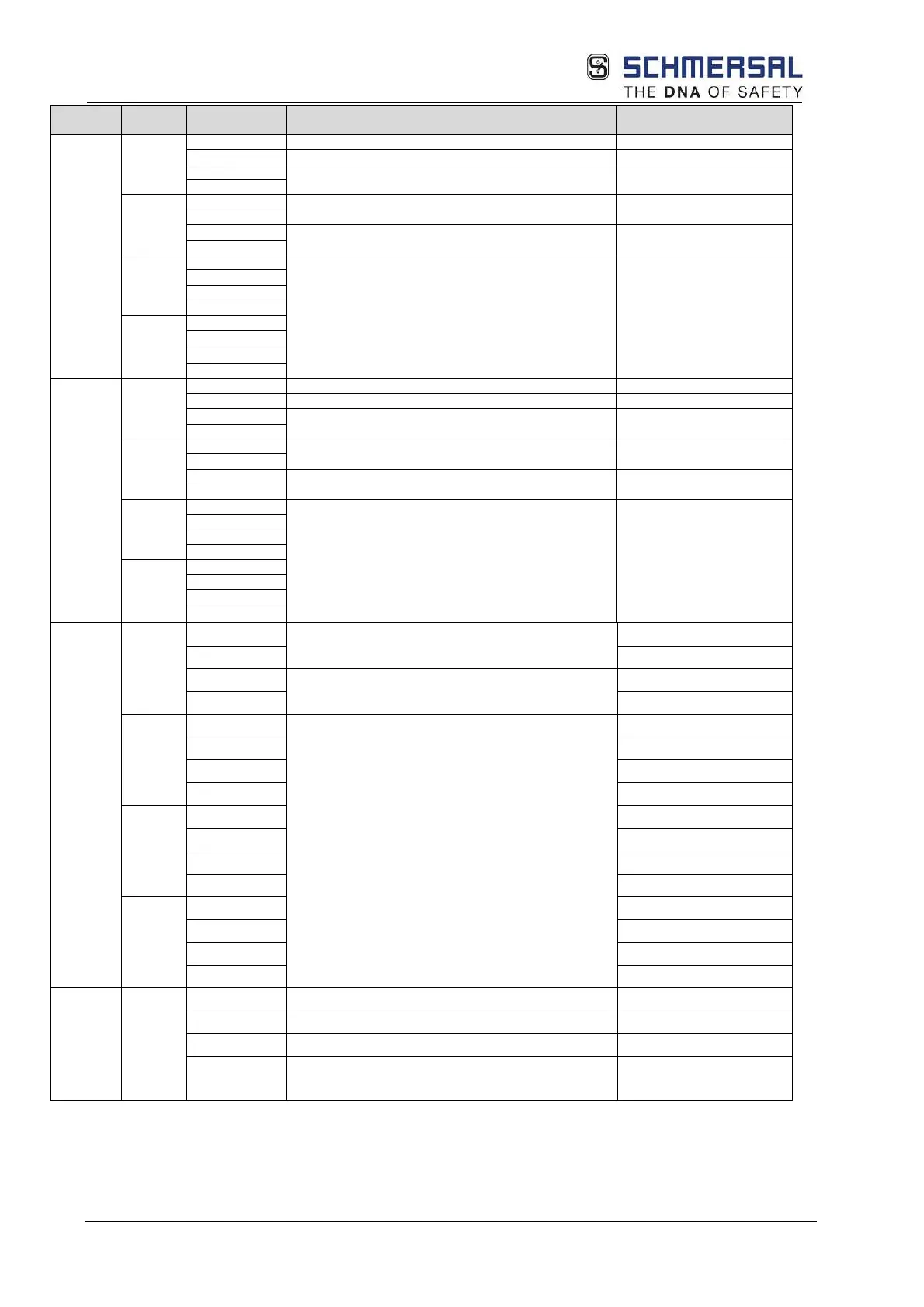
Unit Termina
Pin
Description Note
IO
X45
Device power supply +24 VDC
Device power supply +24 VDC outputs
Device power supply 0 VDC
X46
Safe digital inputs, outputs pp switching
Signal outputs
X47
Safe digital inputs, outputs pp switching
X48
3 – IQ08
IO
X49
Device power supply +24 VDC
Device power supply +24 VDC outputs
Device power supply 0 VDC
X50
Safe digital inputs, outputs pp switching
Signal outputs
X51
Safe digital inputs, outputs pp switching
X52
3 – IQ18
CPU
X65
1 – NC
No function
2 – NC
3 – T0
Pulse outputs
4 – T1
X66
1 – I00
Safe digital inputs
2 – I01
3 – I02
4 – I03
X67
1 – I04
2 – I05
3 – I06
4 – I07
X68
1 – I08
2 – I09
3 – I10
4 – I11
Option
FB1/FB2
X99
1 – A1.3
Power supply SD-Bus +24 V DC
2 – A2.3
Power supply SD-Bus 0 V DC
3 – SD
SD-Bus connection
4 – FE Functional earth
Connect to FE or PE of the
control cabinet (use short