Installation manual
HB-37420-810-01-25F-EN PSC1-C-100 Installation manual - V2.2.docx Page 25 of 201
Version: 25F
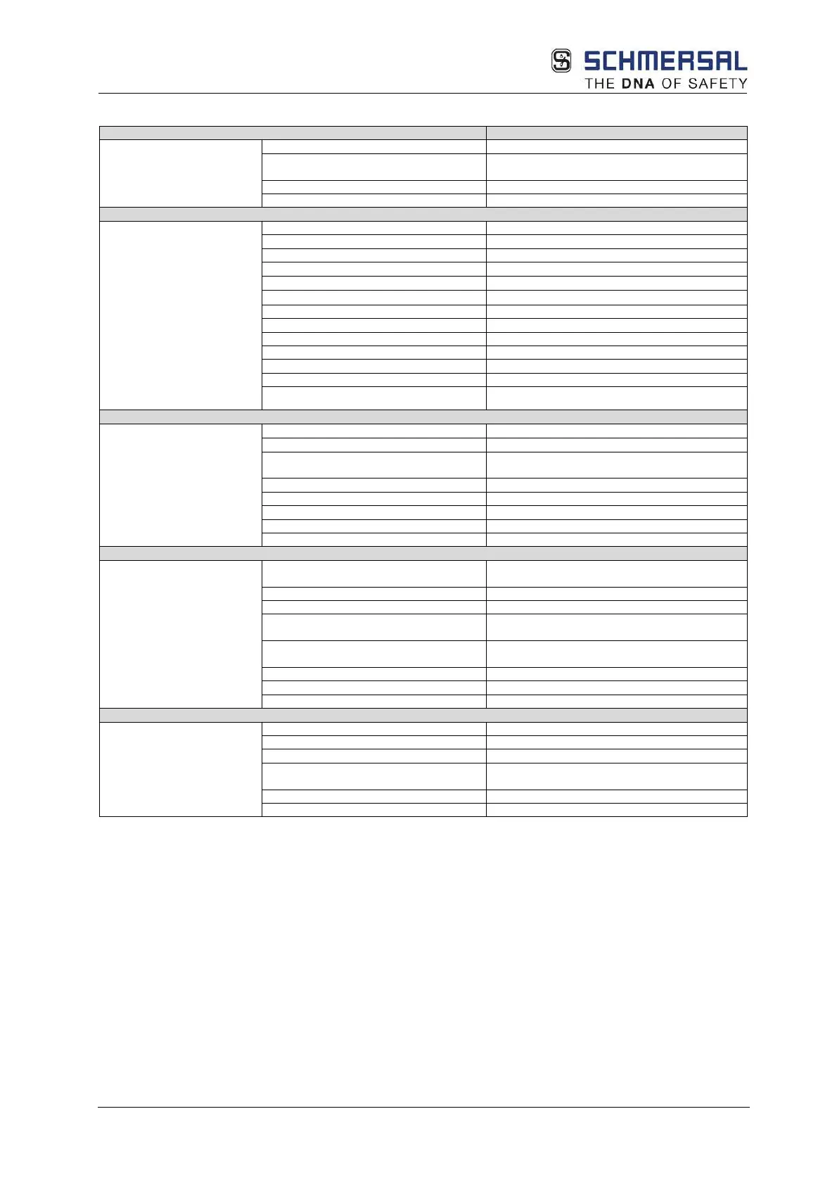
3.7.2.3.1 Tech. characteristic data PSC1-E-23-SDM2
related characteristic data
PFH
(3)
/architecture
3 * 10
-9
(1)
/ KAT 4
-9
(2)
SIL according to IEC 61508
20 years = max. service life
Max. number of expansion modules
Interface for expansion modules
bus connector, can be plugged into DIN rail
Number of safe digital inputs
Number of safe digital outputs -
Number of safe digital I/O
Number of relay outputs (1-channel)
-
Number of safe analogue inputs
Removable screw terminals
(D-Sub / screw terminal)
Encoder technology
(See table Encoder
specifications)
SSI, SinCos, TTL, proximity switch
Supply voltage
(tolerance)
-
(logic)
Rated data digital inputs 24 VDC; 20 mA, type 1 according to IEC 61131-
Rated data digital outputs
Rated data auxiliary outputs
Temperature 0°C … +50°C operation
25C° … +70C° storage, transport
3k3 according to DIN 60 721
Minimum, maximum relative humidity
5% - 85%
EMC EN 61000-6-2, EN 61000-6-4, EN 61000-6-7, EN
Use of operating equipment
(HxDxW [mm])
Can be snapped to DIN rail
Number of T-bus connectors
2
Options:
(*)
Maximum 2 encoders/axis
(1)
1 axis
(2)
2 axes
(3)
Value only applies for expansion module. For an overall assessment according to EN 13849,
a series connection with the related basic device must be used
=> PFH
Logic
= PFH
Basic
+ PFH
Expansion