ILLUSTRATIONS
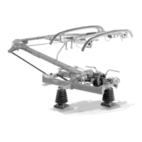
Illustration 1: Components ......................................................................................... 19
Illustration 2: Base frame ........................................................................................... 20
Illustration 3: Lower frame ......................................................................................... 21
Illustration 4: Upper frame ......................................................................................... 22
Illustration 5: Air bellow drive ..................................................................................... 23
Illustration 6: Valve unit ADD ..................................................................................... 24
Illustration 7: Lock cock OPEN - ADD ACTIVATED .................................................. 25
Illustration 8: Lock cock closed - ADD DEACTIVATED ............................................. 26
Illustration 9: Coupling rod ......................................................................................... 27
Illustration 10: Parallel guide...................................................................................... 28
Illustration 11: Pan head ............................................................................................ 29
Illustration 12: Shock absorber .................................................................................. 30
Illustration 13: Cable with terminals ........................................................................... 31
Illustration 14: Shunt .................................................................................................. 34
Illustration 15: Type tag ............................................................................................. 35
Illustration 16: Lifting eye nuts ................................................................................... 40
Illustration 17: EXAMPLE: Base tube of lower frame ................................................. 42
Illustration 18: High voltage connection ..................................................................... 43
Illustration 19: Air connection ..................................................................................... 44
Illustration 20: EXAMPLE: Grease cable with terminals ............................................ 57
Illustration 21: Minimum thickness ............................................................................. 60
Illustration 22: Checkup of shock absorber ................................................................ 62
Illustration 23: UNLOCK test valve ............................................................................ 63
Illustration 24: OPEN test valve ................................................................................. 64
Illustration 25: CLOSE test valve ............................................................................... 64
Illustration 26: LOCK test valve ................................................................................. 65
Illustration 27: Example Replace cable with terminals ............................................... 69
Illustration 28: Replace rod end ................................................................................. 71
Illustration 29: Replace sliding strips ......................................................................... 72
Illustration 30: EXAMPLE: Replace damper .............................................................. 74
Illustration 31: Replacement of shunts ....................................................................... 75
Illustration 32: Shunts between base frame and lower frame .................................... 77