Installation
2–6 700-0042 R004
2.4. Step 3: Installing the Cameras
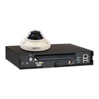
If you have purchased cameras from Seon Design, install the cameras according
to the documentation that shipped with the product.
If you have cameras already installed, see “2.5.2. Checking the Camera Cable
Connections”.
2.5. Step 4: Connecting the DVR
2.5.1. Connecting to the DVR Back Panel
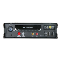
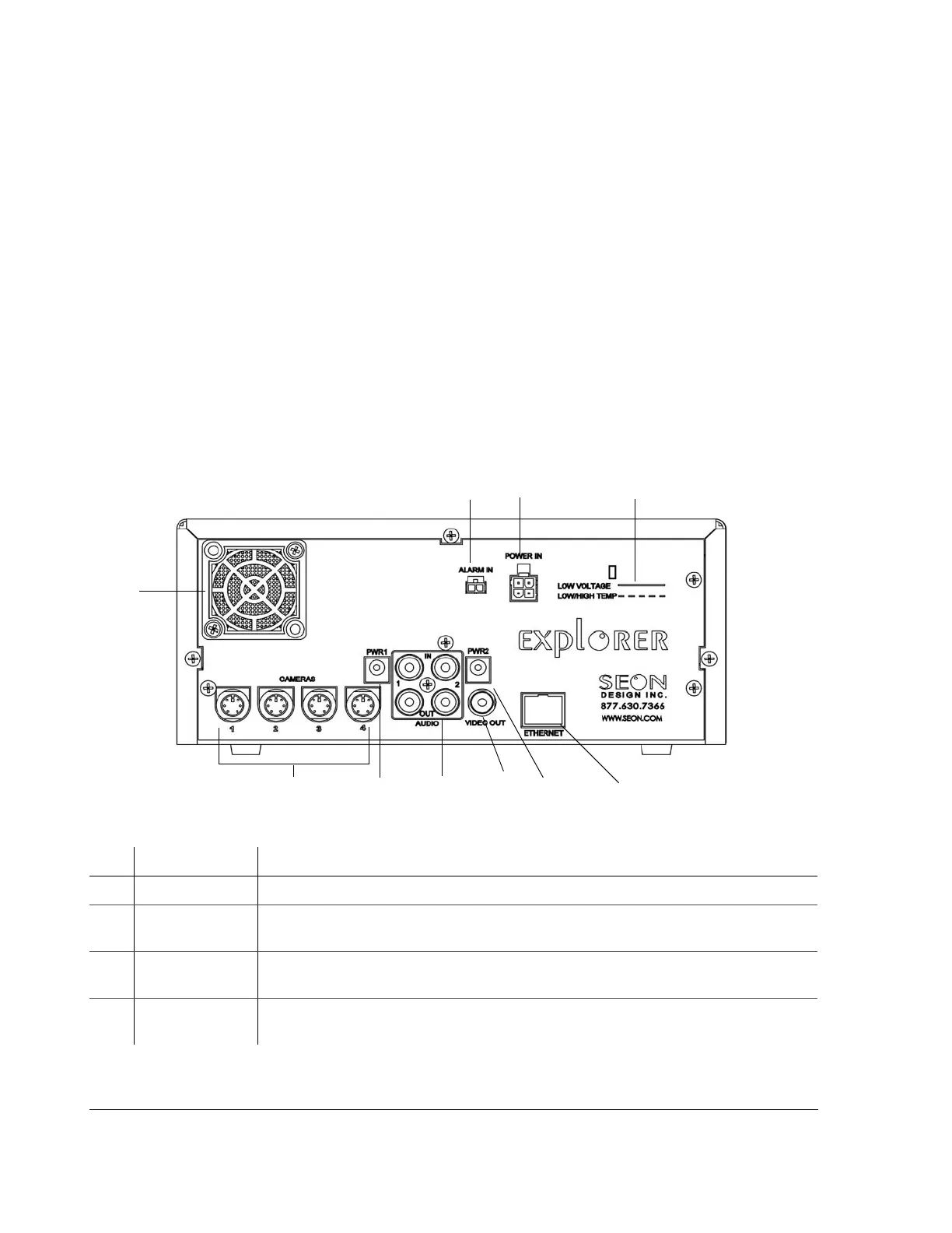
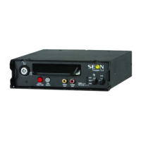
Figure 2-4 shows the back panel of the EX4 DVR which provides the connectors
for the camera inputs, alarm input cable, power input harness, Ethernet, video in
and out, audio in and out, and power.
Figure 2-4
Back panel
Item Feature Description
1 ALARM IN Alarm input connector (2 pins) for connecting the alarm input cable.
2
POWER IN EX4 Plus: Power input connector (4 pins) for connecting the Smart-Link-to-DVR
connection harness.
3
LOW VOLTAGE
LOW/HIGH TEMP
Low voltage and Low/High temperature indicator (red) illuminates if the voltage is low.
(See “4.7. Voltage Display” on page 4–12.)
4
ETHERNET Network connector: RJ-45 for connecting to LAN. Ethernet is used to connect either to a
PC or directly to the wireless bridge equipment.
1
2
3
9
4
5
5
6
7
8