Installation
700-0042 R004 2–9
2.6. Step 5: Connecting the Power and Ignition Harness,
Fuses and Fuse Holders
The power and ignition harness uses a pair of 16 AWG power wires to connect to
the vehicle battery and a 22 AWG yellow wire to connect to an ignition-switched
circuit. See Figure 2-6.
The supplied in-line automotive fuse holders are for protecting the red positive (+)
battery wire and the yellow ignition wire. A 5 A fuse and in-line fuse holder is
supplied for the red positive (+) battery power wire. A 1 A fuse and in-line fuse
holder is supplied for the yellow ignition trigger wire.
To connect the power and ignition harness to the battery:
1. Connect the battery power wires as close to the battery as possible.
The battery acts as a very good filter for transients and surges on the vehicle
power lines. Also, the lines from the battery have a voltage drop across them
because of current drawn by lights, blowers, and A/C units, for example.
2. If there is a master battery switch in the battery compartment connected to the
battery’s negative (–) terminal, then connect the black negative (–) battery
power wire after the battery switch.
3. The in-line fuse holder consists of a black plastic piece with an attached cap
that simply pulls apart. Install the appropriate fuse and push the holder back
together.
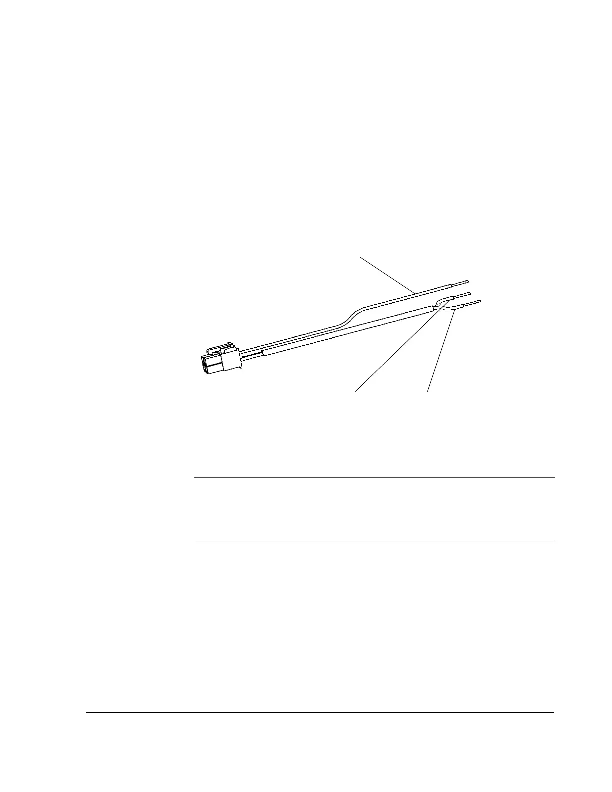
Figure 2-6
Power and ignition harness wires
Black battery wire–Battery negativeRed battery wire–Battery positive
Yellow ignition trigger wire
Important:
Connecting the power farther from the battery results in a larger voltage
drop (reduced voltage from the battery to the DVR). If the voltage drop is too large, then
the DVR detects the low voltage and stop recording to protect itself. If the voltage stays
low for too long, the DVR interprets this as meaning the vehicle battery is drained and the
DVR shuts down completely.