Installation
700-0042 R004 2–13
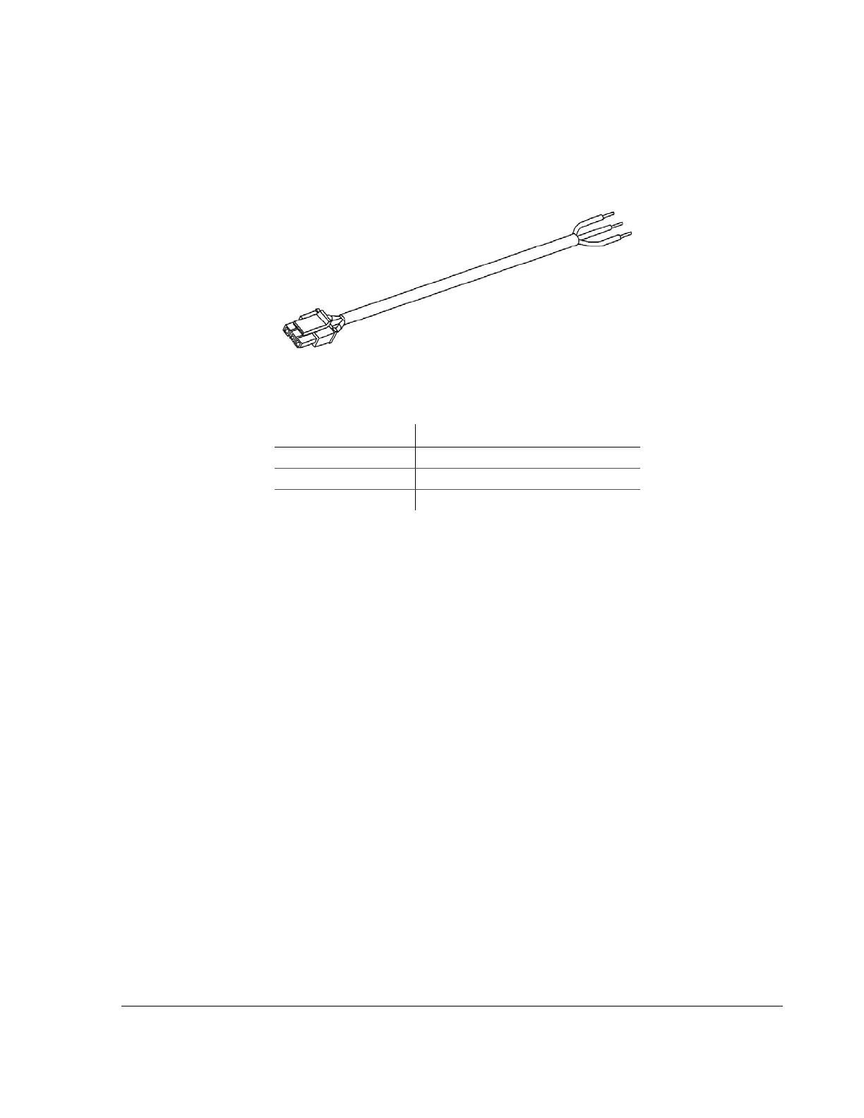
2.7.2. EX4 Plus: Connecting the Speed Cable
The 3-conductor speed sensor cable is for connecting to a transmission control
module or an optional speed signal sensor.
The green speed pulse signal is designed to interface to speed sensors that put out
a pulse signal of up to 20 VDC, 20 VAC
p-p
or speed sensors that use open-
collector style outputs. Contact Seon Design for recommended speed sensors to
use with the EX4 Plus.
All of the wires in the speed sensor cable are protected against short circuits and
transients.Refer to the product documentation that comes with the speed sensor
for further information on connecting to an external speed sensor.
The EX4 DVR has the ability to interface directly to some types of Transmission
Control Modules (TCM) in vehicles. Contact Seon Design for further details
about connecting the speed cable.
2.8. EX4 Plus Step 7: Installing the GPS Receiver
If you have not purchased a GPS receiver or if you wish to install the GPS
receiver at a later time, please proceed to “2.9. EX4 Plus Step 8: Installing the
Driver’s Indicator Panel” on page 2–14.
Seon Design provides several models of GPS receivers designed to work with the
EX4 Plus. Contact your sales representative at Seon Design for the GPS receiver
best suited for your application.
Figure 2-10
20-foot Smart-Link speed cable
Table 2-3
Speed cable wiring
Wire Color Signals
Black Signal ground (0 V)
Green Speed pulse signal
Red Speed sensor power (7.5 VDC)