Chapter 3
MSC800
18 Operating instructions | SICK 8011540/14B8/2019-06-06
Subject to change without notice
3 Product description
This chapter provides information on the structure, properties, and function of the
MSC800.
To help with mounting, electrical installation, and commissioning, and for the
configuration of the logic unit of the MSC800 with the SOPAS-ET configuration software,
read the chapter before starting work.
3.1 Structure of the MSC800
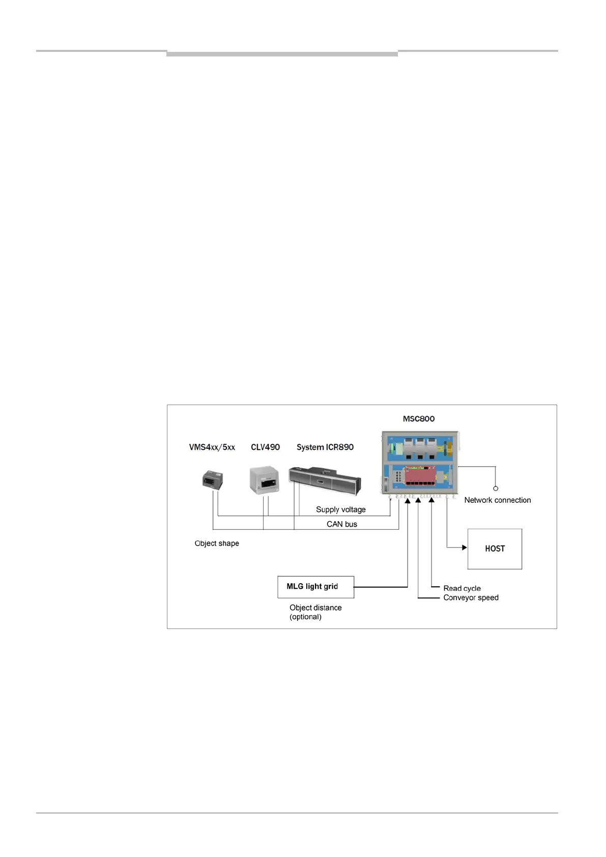
The MSC800 consists of a logic unit and one or more power supply units in a cabinet
(control cabinet). The MSC800 is used in combination with ID sensors and a VMS4xx/5xx
(detection of object shape). In order to do this, the sensors are connected to the MSC800
logic unit via the CAN bus.
The MSC800 power supply unit (supplies) feeds (feed) DC 24 V supply voltage to the
sensors. The MSC800 does not have a main switch for the incoming supply voltage AC
100 ... 264 V / 50 ... 60 Hz.
External sensors are required for the read cycle, for detecting the object distance (with
MLG, alternative to the VMS4xx/5xx, application-dependent), and for generating an
increment signal. These sensors and the superordinate host computer are also connected
to the MSC800.
Fig. 1: MSC800 in combination with ID sensors and external sensors